Real-time efficiency measurements of electric vehicle inverters and motors
Mileage anxiety is one of the hot topics in the electric vehicle industry. How to improve the range of electric vehicles and thus the driving experience is crucial for electric mobility, where optimizing the operating efficiency of inverters and motors is one of the cornerstones of electric vehicle energy management. This paper will introduce how to use Vector-CSM’s EV high voltage measurement system to perform accurate real-time efficiency analysis of inverters and motors.
Background
In order to improve range, the components of an EV powertrain need to be optimized. Inverters play an important role in the overall powertrain. A high-efficiency inverter can reduce losses in the energy conversion process between the battery and the motor, such as during the drive process, where some energy is lost due to PWM switching performance and waste heat, and during the braking process, where the inverter can recover energy to charge the battery on demand, a process that also involves energy losses. Measuring the efficiency of the inverter and motor provides a reference for evaluating and validating EV powertrain designs and optimizing control software algorithms.

The Challenge
In order to perform accurate real-time power calculations for the EV powertrain, the current and voltage at the input and output of the object under test need to be measured at high sampling rates, and the signals need to be synchronized and phase-accurate. For comprehensive analysis, other measurements, such as temperature in the inverter, need to be acquired simultaneously to observe and capture the operating threshold of the component and the efficiency at a specific temperature. Ideally, the measurement modules should be arranged close to the sensors to avoid electromagnetic interference caused by long signal transmission cables. Also measurements in high voltage environments must ensure the safety of the subject, the measurement equipment and the user.
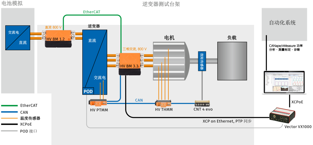
Figure 1:Vector-CSM Electric Vehicle High Voltage Measurement System
The HV BM module can measure single-phase and three-phase voltages and currents simultaneously, in conjunction with the power analysis function library in vMeasure software for accurate analysis.
The HV BM 1.2 module is connected between the battery and the inverter by means of a Glan head or a PL500 type connector. HV BM 1.2 modules measure single-phase DC and voltage in HV+ and HV- and transfer the data via EtherCAT at a data rate of 1 MHz. (Plug-and-play of the module is possible by installing the appropriate connector plug)
The HV BM 3.3 module is connected between inverter and electric drive by means of a Glan connector or a PL300 type connector and is secured by an interlocking protection device with simple wiring. The measurement module supports the synchronization of current and voltage phases of three-phase AC power and is capable of transmitting at 2 MHz data rate via XCP-on-Ethernet.
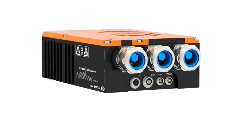
Figure 2: HV BM 3.3 measuring the three-phase AC between the inverter and the motor
The High Voltage Safety Temperature Module (HV PTMM) measures the temperature in the inverter.
The >HV BM 3.3 (with XCP gateway) module provides additional EtherCAT and CAN interfaces, allowing the HV BM 1.2 module (via EtherCAT) and the HV temperature module (via CAN) to be connected to the HV BM 3.3 module, achieving a synchronization accuracy of less than 1µs for both HV BM modules.
The frequency measurement module (CNT 4 evo) calculates motor efficiency by measuring torque and speed and can be connected directly to the CAN interface of the HV BM 3.3 module.
VX1000 can collect internal variables of the motor controller and synchronize precisely with HV BM measurement data via PTP.
CANape and vMeasure comes with eMobitlityAnalyzer function library for real-time efficiency calculation.
HV BM 3.3 supports the three-phase power calculation function. The phase current and line voltage measured synchronously are sent to the host computer at a rate of 2 MS/s via XCP, and the electric power calculation, such as active power, apparent power, reactive power and power factor, is done in real time using the eMobilityAnalyzer function library.
Along with the inverter efficiency analysis, the eMobilityAnalyzer library calculates all necessary parameters such as input power and energy, output power and energy, power dissipation, energy loss, efficiency, and rotating magnetic field frequency.
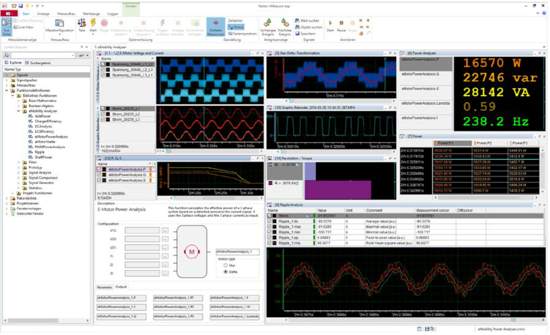
Figure 3: vMeasure software comes with eMobilityAnalyzer function library for power analysis
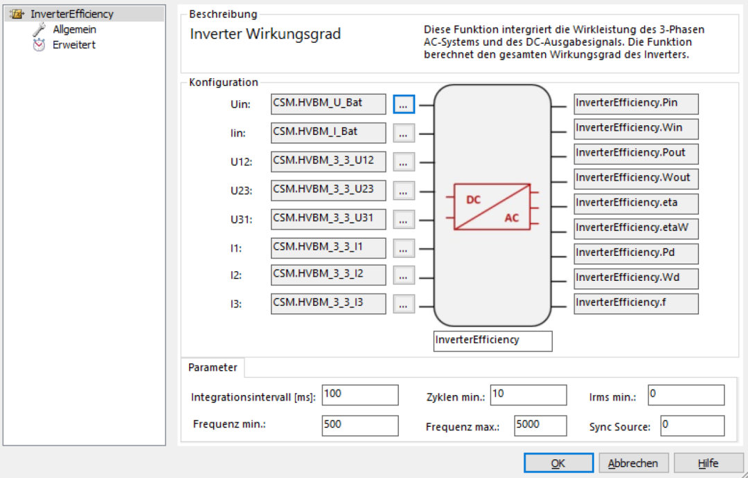
Figure 4: Inverter efficiency analysis using the eMobilityAnalyzer function library
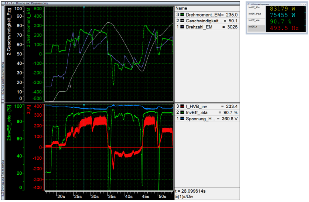
Figure 5:Test data of an electric vehicle (nominal power of 75 kW) obtained according to the Vector-CSM measurement system (Figure 1). The speed curve (white) reflects vehicle acceleration and deceleration. The corresponding red color shows the forward or reverse current. During drive, the inverter efficiency (bright green) exceeds 90% at high loads; and during energy recovery, the inverter reverse charging efficiency (bright green) can be as high as 90%. When the load changes to a lower current, the inverter efficiency and charging efficiency become worse. The eMobilityAnalyzer function library (Figure 4) allows real-time and offline power calculations, as well as the current frequency of the motor.
Benefits
The Vector-CSM EV high-voltage measurement system supports distributed measurements on the bench or in the vehicle, and Vector’s software solution allows precise synchronization of the data collected by the CSM module with the internal data of the ECU.
HV BM modules can be plugged into the test environment via plug-and-play connectors, and the objects under test can be quickly changed to meet different test configurations.
In addition, other measurement modules can be connected directly to HV BM 3.3 or HV BM 3.3C, further simplifying the test environment configuration. The HV BM module directly measures current and voltage and performs real-time power analysis, replacing cumbersome traditional power analyzers and current conversion systems.
In high-voltage environments, the Vector-CSM electric vehicle high-voltage measurement system not only ensures a secure measurement link from sensor to data acquisition, but also provides easy expansion of the test module and always ensures synchronization of the measurement signal. With real-time efficiency calculations, users can conveniently check and optimize the components in the electric drive test stand. In addition, the CSM module is suitable for on-board use and facilitates comparison of bench data with real vehicle data.
Vector offers you a comprehensive measurement test solution including measurement modules, sensors, connection cables and software – the final solution is customized according to your individual needs.