Chapter 1, EMC concept introduction
EMC (electromagneTIc compaTIbility) as a characteristic of the product, translated as electromagnetic compatibility; if as a discipline, it is translated as electromagnetic compatibility. It includes two concepts: EMI and EMS. EMI (electromagneTIcinterference)
EMI (electromagneTIcsusceptibility) electromagnetic susceptibility, also known as electromagnetic immunity, refers to the degree to which it can tolerate electromagnetic interference from other electrical products. Therefore, EMC is used to filter out the external electromagnetic interference (radiation + conduction) introduced from the power line on the one hand, and to avoid noise interference from the equipment itself to the outside so as not to affect the normal operation of other electronic equipment in the same electromagnetic environment.EMC filter is mainly used to filter out the conduction interference, inhibit and attenuate the noise signal generated by the outside world to interfere with and affect the protected equipment. At the same time, it suppresses and attenuates the interference generated by the equipment to the outside world. And radiation interference is mainly filtered out by means of shielding.

From the function of the filter, its role is to allow a certain part of the frequency of the signal to pass smoothly, while another part of the useless frequency of the signal is subject to greater inhibition, it is essentially a frequency selection circuit. And we commonly low-pass filter function is to allow the low-frequency or DC component of the signal to pass, inhibit the high-frequency component or interference noise.
Power supply noise interference is common in everyday life. For example, you are using the computer, when the phone signal appears, the computer audio will have noise. For example, there is a sizzling noise when talking on the phone or cell phone. Another example is when using a hair dryer to iron your hair, the TV will not only produce noise, but also the screen will appear very large snow-like streaks. These are some common noise signal interference, but in fact some interference can not be seen on a daily basis, but once affected by the possibility of being caught off guard, or even find the root cause. These noise signals if the appearance of automated instruments, medical instruments have the potential to bring great losses and even life safety. For example, it can cause the automated instrumentation to malfunction, causing medical instruments out of control and so on.
We often say that noise interference, is a general term for all electronic signals other than useful signals, can also be understood as electromagnetic interference. Initially, people caused the radio sound equipment issued by the noise of those electronic signals, called noise. However, the consequences of some non-useful electronic signals on electronic circuits are not always related to sound, so later people gradually expanded the concept of noise. For example: a frequency of the radio wave signal, the need to receive this signal for the receiver, it is normal useful signal, and for another frequency receiver it is a useless signal, that is, noise.

Noise according to the propagation path can be divided into conducted noise interference and space noise interference. The conductive interference mainly through the conductor propagation, through the conductive medium to an electrical network on the signal coupling (interference) to another electrical network, the spectrum is mainly below 30MHz. Conducted noise interference can be suppressed and attenuated through the design of filter circuits or additional filters, while space radiation interference is mainly through the main application of sealed shielding technology, the implementation of electromagnetic closure in the structure. At present, in order to reduce the weight of most of the aluminum alloy shell, but the aluminum alloy conductivity is poor, so the shell needs to be plated with a layer of nickel or spray conductive paint, the inner wall is coated with high permeability shielding material.

Above we mentioned conducted noise interference, which is further divided into two types of differential mode interference and common mode interference. Differential mode interference is the noise between the two power lines (referred to as line-to-line), mainly through the selection of appropriate capacitance (X capacitor), differential mode coil to suppress and attenuate. Common mode interference is the noise between two power lines to the earth (referred to as line-to-ground), mainly through the selection of appropriate capacitors (Y capacitor), and common mode coils to suppress and attenuate. Our common low-pass filter generally has the function of suppressing both common mode and differential mode interference.
Chapter 2, inductive interference (near field)
Section II nuisance transmission through space
A. The difference between near-field and far-field
Harassment through space transmission is essentially a strong source of electromagnetic energy in the form of field propagation to the surrounding space. Service can be divided into near-field and far-field. Near field is also known as the induction field, the nature of the near field and the nature of the field source is closely related to if the field source is a high-voltage source of small currents, the near field is mainly electric field. Figure 2-20 is a signal source to a short dipole antenna, antenna poles between a certain voltage but the current is small, mainly the displacement current in space near the dipole antenna electric field is larger than the magnetic field. We commonly use wave impedance to describe the relationship between the electric and magnetic fields, wave impedance is defined as
Z. – E / H (2-22)
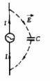
here because the electric field is much larger than the magnetic field, so the wave impedance is higher, so the electric field source is also called high impedance Yang source, around 2-20 short even with the distance from the antenna increases electric field and magnetic field will be reduced, but Eoc1 / and H1 / because the polar antenna structure of this wave impedance with distance plus and reduce.
The electric field source if the field source is a low-voltage, high-current source, the near field is mainly magnetic field. Figure 2-2] is a signal source to a small loop antenna, the antenna current is larger, the antenna perimeter map of the magnetic than the electric field, wave impedance is low, so the magnetic field source is also known as a low-impedance field source. As the distance from the antenna increases the electric field and magnetic field are reduced, but Eoc1/ and Hc1/ so the impedance increases with distance

State 2-21 shape
Regardless of the field source is the electric Yang source or magnetic field source, when the distance from the field source is large antenna composition in A/2* after the field has become far field, also known as radiation field. At this time, the electric magnetic Yang source field and magnetic field direction perpendicular and are perpendicular to the direction of propagation called plane wave, as shown in Figure 2-22 electric field and magnetic field ratio for a fixed value, that is, the wave impedance Z-120 yuan = 377 (0), electric field and magnetic field with 1// rate decreases with distance, so the far field is also called electromagnetic field. The variation curve of wave impedance with distance is shown in Figure 2-23 In summary, the criterion for determining the near-field far-field is
Figure 2-22 Electricity in the transport field
Field, comfort and transmission
r>A/2m Far field
The relationship between the direction of
r<A2- Near field

Far field is a plane wave, easier to analyze and measure, only need to measure the electric field to calculate the magnetic field, and vice versa. Near field is more complex, electric field and magnetic field are not easy to convert each other, need to be measured separately, at the same time, because of the near field field strength and 1/P or 1/related so the position of the emblem of small changes will cause a large measurement error, for the distance between the system of electromagnetic compatibility problems are generally used to analyze the far field. For the system, especially the same equipment within the problem is basically a near-field paste problem.
Common electric fields Such as two metal plates with a voltage across them.
Common magnetic fields Such as the magnetic field between two magnets
The speed of an electromagnetic wave is close to the speed of light in air. Wavelength = c/f = 3×10⁸/f = 300/F (MHz) e.g., F = 10 MHz Wavelength = 30 m r = wavelength/2*3.14 = 4.77 m.
Frequency of 10MHz electromagnetic wave emission source, in the distance from the source is greater than 4,77 meters, for the far field, less than 4,77 meters, for the near field.
Chapter 3, radiation interference (far field)
3.1. Principles and causes of generation

According to Maxwell’s equations, a changing electric field produces a changing magnetic field, and a changing magnetic field produces a changing electric field.
Each circuit within the device could be an antenna, and both the enclosure and the cable could be part of the antenna.
My understanding is that electrostatic and static magnetic fields only interfere with equipment in close proximity.
Alternating electric and alternating magnetic fields do not only interfere with equipment in close proximity, but also with equipment at great distances.
Whether it is electric field interference or magnetic field interference after the long-distance propagation, are in the form of alternating electromagnetic field propagation.
Electromagnetic field explanation
Electromagnetic field has an intrinsic link, interdependent electric and magnetic fields of the unity and general term. The time-varying electric field produces the magnetic field, the time-varying magnetic field produces the electric field, the two are mutually dependent, forming the electromagnetic field. Electromagnetic field can be caused by the variable speed movement of charged particles, can also be caused by the strength of the changing current, regardless of the cause, the electromagnetic field is always the speed of light to the surrounding propagation, the formation of electromagnetic waves. Electromagnetic field is the medium of electromagnetic action, with energy and momentum, is a form of material existence. The nature of the electromagnetic field, its characteristics and its law of motion change is determined by Maxwell’s set of equations.
3.2. How to affect the equipment
Sensitive equipment by space interference
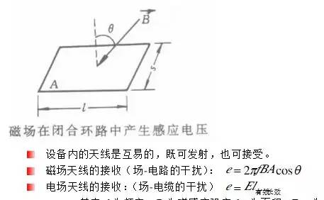
Where f is the frequency B is the magnetic induction strength A is the area E is the electric field strength
3.3. How to filter out radiation interference
Such as in the source and sensitive equipment peripheral shielding, isolating the radiation path; and in sensitive equipment ports to increase the filter circuit, to prevent the noise has been coupled to the port into the device.
3.4. How to reduce radiation interference
Method 1: The use of coaxial cable twisted cable stranded cable.
Such as MR6; IDM11 cable line is stranded cable

Method 2: should minimize the useful signal of the higher harmonic components (the higher the frequency, the stronger the radiation)
Method 3: Take shielding methods
Ventilation port, try to use small round holes, avoid using long ventilation holes.
General filter schematic diagram
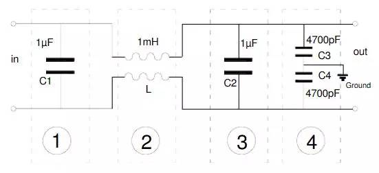
As in Figure 1, 3 is the differential mode capacitor, 2 is the common mode inductor, and 4 is the common mode capacitor.
Generally, the filter does not use the differential mode coil alone, because the common mode inductor is not the same on both sides of the winding and other reasons, the inductance must not be the same, so it can play a certain role of the differential mode inductor. If the differential mode interference is more serious, additional differential mode coil.
Chapter 4: Differential Mode Interference
4.1 Differential-mode interference: simply put, it is a line-to-line interference.

The UDM is the differential mode voltage and the IDM is the differential mode current. the IDM is the same size and opposite direction.
4.2 Causes of Differential Mode Interference
Differential mode interference originates in the same power line (direct injection). Such as the same line of work in the motor, switching power supply, thyristor, etc., they are in the power line generated by the interference is the differential mode interference.
4.3 How to affect the equipment.
Differential mode interference acts directly on both ends of the device, directly affecting the work of the device, or even damage the device. (Expressed as spikes, voltage dips and interruptions.)
4.4. How to filter out differential mode interference
The main use of differential mode inductors and differential mode capacitors.
4.4-1 Differential mode inductor principle of operation:

It can be seen that after the current flows through the differential mode coil, the magnetic flux inside the coil is enhanced, which is equal to the sum of two magnetic fluxes.
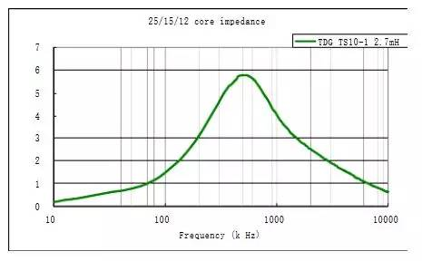
The coil characteristic low frequency low impedance high frequency high impedance determines the use of its high impedance to attenuate the differential mode signal at high frequencies. (As shown in the figure below).
When the frequency is 50Hz, the coil impedance is close to 0, which is equivalent to a wire and does not have any attenuation effect.
When the frequency is 500kHz, the impedance reaches 5k ohms, while the ideal state, the load impedance is generally considered to be 50 ohms.
According to the above formula, at this time, the differential mode coil shares 99% of the differential mode interference voltage, while the load only shares 1% of the differential mode interference voltage.
At the same time, the current also has a large attenuation. (can be calculated at this time the coil of differential mode insertion loss)
4.4-2 Principle of operation of differential mode capacitor.

As you can see, the capacitor characteristic low frequency high impedance high frequency low impedance. The filter takes advantage of the capacitor’s low impedance at high frequencies to short out differential mode interference. (As shown in the diagram below:)
When the frequency is 50Hz, the capacitor impedance tends to infinity, which is equivalent to a short circuit and does not have any attenuation effect.
When the frequency is 500kHz, the capacitive impedance is very small, according to the above formula, we can see that the current attenuation of the differential mode load is close to 0.
When the frequency is 500kHz, the capacitive impedance is 0.05 ohms for a load of 50 ohms.
At this time, the capacitor shares 99.9% of the differential mode interference current, while the load only shares 0.1% of the differential mode interference current.
In other words, at 500kHz, the capacitor makes the differential mode interference drop by 30dB.

Chapter 5, common mode interference
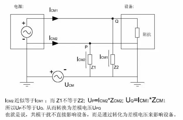
5.1. Common mode is the common to ground interference.

As shown in the figure, we can see the schematic of common mode. UPQ is the common mode voltage, ICM1ICM2 is the common mode current.
ICM1ICM2 size is not necessarily the same, the direction is the same.
5.2. There are many reasons for common mode interference.
The main reasons are as follows.
- The grid string into the common-mode interference voltage
- radiation interference (such as lightning, equipment arc, nearby radio stations, high-power radiation sources) in the signal line to induce common-mode interference.
(The principle is that the alternating magnetic field produces alternating current, due to the ground – zero circuit area and ground – fire circuit area is not the same, the two circuits are different impedance and other reasons caused by the current size is different) - The ground voltage is not the same. That is, the ground potential difference introduced common-mode interference.
- also includes the impact of the internal wires of the equipment on the power line.
5.3. How to affect the equipment.
Common mode voltage is sometimes larger, especially the use of poor isolation performance of the distribution power supply room, the transmitter output signal common mode voltage is generally higher, some can be as high as 130V or more. Common mode voltage through the asymmetric circuit can be converted into differential mode voltage, directly affect the measurement and control signal, resulting in component damage, this common mode interference can be DC, but also for AC.
As Figure
5.4. How to filter out common mode interference (common mode coil common mode capacitor)
5.4-1 Common mode coil

Common mode coils and differential mode coils are relatively similar in principle, both using the high impedance of the coil at high frequencies to attenuate interference signals. The common mode coil and the differential mode coil winding method is just the opposite (see figure).
Because differential mode coils filter out interference while also increasing impedance to some extent, while common mode coils do not work for currents in opposite directions, so we generally rarely use differential mode coils as long as they can meet the characteristics.
Literature I: In this way, when the normal current in the circuit flows through the common-mode inductor, the currents in the inductor coil wound in the same phase to produce the opposite magnetic field and cancel each other out, when the normal signal current is mainly affected by the coil resistance (and a small amount of damping due to leakage inductance); when there is a common-mode current flowing through the coil, due to the common-mode current in the same direction, it will produce the same direction of the magnetic field in the coil and increase the inductive resistance of the coil, so that the coil When there is a common mode current flowing through the coil, due to the homogeneous nature of the common mode current, it will increase the inductance of the coil by increasing the magnetic field in the same direction, so that the coil will show high impedance and produce a strong damping effect to attenuate the common mode current and achieve the purpose of filtering.
Literature 2: We know the current law, we also know that the flux generated by the current, and we know that the same size, the same number of turns, the flux generated by the current in different directions will cancel each other, resulting in the whole common mode coil does not work for the current in different directions, and just let it pass; but for the flux generated by the current in the same direction, because the flux direction is the same, the flux does not cancel, so some common mode coils play the role of impedance Therefore, the common mode coil acts as an impedance, suppressing the spurious current in the same direction to achieve the purpose of anti-electromagnetic interference.
5.4-2 Working Principle of Common Mode Capacitor

The working principle of common mode capacitor is the same as that of differential mode capacitor.
Both use the high frequency low impedance of the capacitor to short circuit the high frequency interference signal, while the circuit is not affected at low frequency.
Only the differential mode capacitor is a short circuit between the two poles.
The resonant frequency point of common mode capacitor is 19.3MHz at 3300pF1.6mm pin.