Abstract: A detailed introduction to the ISP function of Philips P89C664 microcontroller combined with Flash Magic software, as well as a detailed description of the technique of using the P89C664 hardware I2C interface to receive data and forward it to the computer for automatic saving of large amounts of data on the I2C bus, with a complete list of source programs and the necessary comments.

Introduction
Translated with www.DeepL.com/Translator (free version)
In practice, some cases may need to analyze the data sent by some I2C interface, if the data is relatively small is relatively easy to solve. For example, you can save the data directly into the RAM of the microcontroller and then display it through LEDs, but if the amount of data is large, this method is very river taking. In this case, find a way to save a large amount of data to the computer is a better way so that not only can solve the problem of storing large amounts of data, but also easy to edit, analyze and print.
Translated with www.DeepL.com/Translator (free version)
However, there is no I2C interface in the peripheral interface of the computer, so it is necessary to convert the data that the I2C department hesitates to send to the computer and realize the file storage of the data. Considering all factors, it is more convenient to use the UART serial interface because the serial interface technology is simple, widely used, and rich in various application software.

This article not only introduces how to achieve I2C data forwarding and automatic storage, but also introduces the ISP function of the P89C664, and gives details with the relevant software, which can completely save a pricey programmer and practicality. This is ideal for amateur self-learning microcontroller technology or at home noisy to build a simple and practical development system.
1 P89C664 microcontroller and ISP, IAP Introduction
P89C664 is an excellent 51 core microcontroller chip from Plilips, with 64KB Flash program summer, 1792B data memory, I2C hardware full working mode interface, 6 clocks/12 clocks optional, 8 interrupt sources/4 interrupt priority levels, dual DPTR registers, PCA and IAP, ISP functions, etc. Please refer to the related resources for details. Detailed technical information and various application documents can be downloaded from the Philips website: http://www.semiconductors.philips.com/.
The following section briefly introduces the concept of ISP and IAP.ISP (In System Programming), that is, in-system programming. It allows the MCU to download a new program while it is still on the product board. One of the advantages of this technology is that there is no need to remove the MCU chip from your board and install it on a traditional programmer to write a new program. You can solder the MCU chip with ISP function on the board, which is more reliable and convenient to apply. Of course, you have to set aside the UART serial port of the MCU and design a simple peripheral circuit; there is also a special ISP software to realize the direct download of user programs. The ISP software for the P89C664 can be downloaded from the Philips website for free. Of course, if you are interested, you can also design your own customized ISP download software, as Philips is open to various programming instructions for ISP.
IAP (In Application Programming), or In Application Programming. That is, the MCU itself can acquire new code and reprogram itself. This is an extremely useful technology, such as the ability to upgrade your product remotely via the Internet, programmed telephone network, etc., just as common antivirus software can be upgraded automatically. With this technology, you can use the current programmed telephone network, the Internet, etc. to realize your embedded system remote automatic upgrade, without the traditional kind of inconvenience caused by mailing the chip to customers.
It is important to point out that the core technology of ISP and IAP is the same, both of them call the internal standard program to erase and reprogram the Flash memory. The difference is that ISP is done by a default serial loader cured on-chip, while IAP is done by the user in his own program, which provides the possibility of remote upgrade and can even be said to be a milestone in MCU application technology.

2 Application of ISP Technology
For Philips’ MCU, its ISP circuit is simple, which is a circuit to communicate with the serial port of the computer (Note: the circuit will be slightly different depending on the ISP control software), and the circuit is shown in Figure 1.
The Embedded Systems Academy provides an ISP software, Flash Magic, which can be downloaded from the organization’s website at http://www.esacademy.com/. The connection circuit above is also used with this software. This is excellent software that is easy to use and powerful, and it supports almost all of Philips’ devices with ISP. Alternatively, Philips also provides ISP software for free, but it is not as easy to use as Flash Magic.
The installation process of Flash Magic is similar to that of standard Windows software and will not be described in detail here. After the installation is complete, Flash Magic is launched with the screen shown in Figure 2.

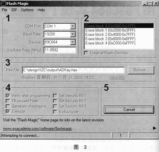
Immediately afterwards the Flash Magic software will try to connect to the ISP chip using the default settings, as shown in Figure 3.
Please note the status bar display “Attempting to connect…” which indicates that Flash Magic is trying to connect to the ISP device. If you have already downloaded the program with Flash Magic and have not changed the ISP device, you will be able to connect in no time. If you are using it for the first time, you need to do some necessary settings so that Flash Magic can connect to the MCU with ISP properly, if you can’t connect, Flash Magic will pop up the box shown in Figure 4.
Please click “Cancel”! Then select the menu Options/Advanced Options… in the main screen of the software. as shown in Figure 5.
The settings box will pop up, please switch to the Hardware Config tab, as shown in Figure 6.
Make “Use DTR and RTS to control RST and PSEN”, “Keep RTS asserted while COM Port open” options are valid, no need to change anything else. If you do not want to change anything else, just click “OK” to confirm.
The main interface of Flash Magic has clear indication of 1, 2, 3, 4, 5 numbers. The numbers from 1 to 5 do not indicate the 5 different areas, nor are they the 5 steps of the download process. Of course, if you have already set it up, you can just click the “start” button after each download.
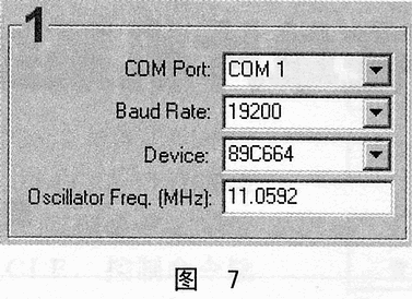
In area 1, we need to set each option here, here we are taking P89C664 as an example, as shown in Figure 7.
COM Port: Flash Magic supports 4 serial ports, COM1, COM2, COM3 and COM4, in most computers there are only COM1 and COM2 ports, the master selects the correct COM port, which is the one connected to the user board.

Baud Rate: Set the download rate of the program here, choose a suitable value according to the situation, it is not easy to be too big, otherwise it will be unable to connect due to interference, usually 19200bps is more suitable.
Device: Select the ISP device model, in Flash Magic version 1.81, 35 kinds of ISP devices are supported, here select P89C664.
Oscillator Frea.(MHz): Please fill in the frequency value of the MCU on your user board.
Other parts are similar, you can download the next Flash Magic by yourself, the new since the operation will be very clear.
In addition to downloading the user program, Flash Magic also provides some other functions, all together in the “ISP” menu. Try it yourself, and you will find that Flash Magic is really useful. It will definitely make your development work twice as easy and save you an expensive programmer, especially for beginners of microcontrollers.
3 I2C receives data and forwards it to the computer
Since the P89C664 comes with a hardware I2C interface, we use it as a slave device to receive data on the I2C bus, and Philips gives a standard I2C interface control program package in the related technical data. In fact, you can also write your own I2C interface control program based on the P89C664 data, but the reference program provided by Philips is worth studying and researching. The following program is the I2C interface control program from Phlips, in order to be more suitable for receiving large quantities of I2C bus data, we have made the necessary changes to part of the code, if you need the standard control program please download it from the Philips website.
The procedure is to first set the address of the I2C interface and the value of each SFR, then start the I2C interface and send the received data to the computer through the serial port, start another serial debugging software on the computer and do the relevant settings, then the I2C bus data can be received and saved. Here, our user board is equivalent to a protocol conversion device, i.e. converting the I2C bus data stream to UART data stream and sending it to the computer.
Please note: Generally, our ISP download and serial debugging are common to the same part of the circuit and the same serial port. Therefore, Flash Magic and serial debugging software can not be started at the same time, otherwise there will be errors. Please close Flash Magic software after downloading the program and then start serial debugging software.
Since serial port has always been a standard interface provided by various computer systems, debugging software for serial port is available everywhere on the Internet, and of course you can design your own serial debugging software if you are interested.
Here we use a serial debugger named COMPort Debuger, the English name of the software, more useful, and has a large number of automatic data saving function, this function is very important. The interface of this software after starting is shown in Figure 8.
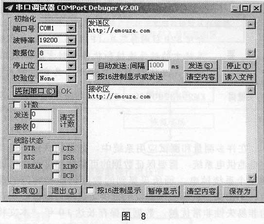
In the transmitting and receiving area, the website of the software author is displayed, you can go there to download the latest version.
After the user board program is running and the serial port is set up for debugging, you can click “Open serial port”, and then various data sent through the serial port will be displayed in the receiving area.
The website (www.dpj.com.cn) gives the finished source program of the P89C664 in the forwarding device with necessary comments.
Conclusion
This article describes in some detail the application of the P89C664 ISP function and the use of a simple online download device programmed to achieve data forwarding and saving on the I2C bus; it also gives a detailed initialization of the I2C hardware interface and the source program for the complete device. It can be used for automatic saving, editing, analyzing, printing, etc. of various high-volume I2C bus data, and can also be used in general development to test whether your program meets the requirements.