Continuous glucose monitoring systems (CGMS) are becoming increasingly popular in the management of diabetes compared to traditional self-glucose monitoring systems (SBGMS). The existing continuous glucose monitoring systems on the market can be divided into two categories according to their working principle: needle-based systems with a lifespan of a few weeks (e.g. the enzyme-based Freestyle Libre) and implantable systems with a lifespan of a few months (e.g. the fluorescence-based Senseonics).
To overcome the shortcomings of existing needle-based and implantable continuous glucose monitoring systems, researchers from the Ulsan NaTIonal InsTItute of Science and Technology and Seoul NaTIonal University in Korea have proposed an alternative electromagnetic-based system to overcome the shortcomings of existing needle-based and implantable continuous glucose monitoring systems, according to McMasters Consulting. Researchers from Ulsan NaTItute of Science and Technology and Seoul NaTIonal University have proposed an alternative sensor solution based on electromagnetism. The proposed sensor is said to be subcutaneously implantable and capable of tracking small changes in dielectric constant due to changes in blood glucose levels (BGL).

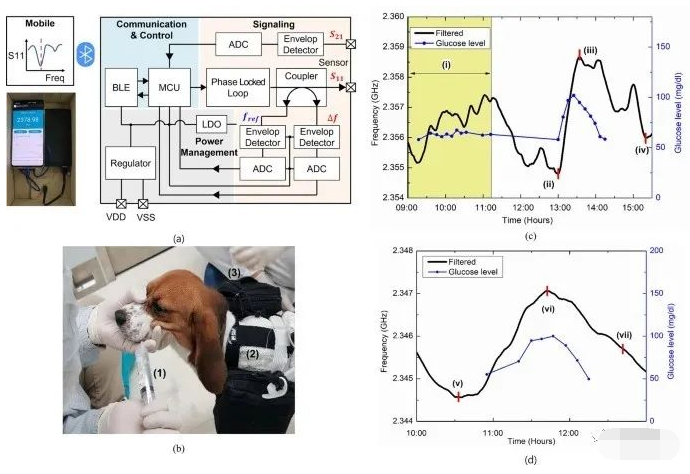
Firstly, the researchers designed and simulated the sensor using the full wave electromagnetic simulation software “CST Microwave Studio”. The sensitivity of the sensor was then optimised to the maximum extent possible in the ISM band (a radio communication band opened by governments to industrial, scientific and medical institutions), taking into account its application in biological environments similar to those consisting of muscle and fat (for the purpose of this study, sensitivity is defined as the change in resonant frequency of the sensor caused by a small change in the dielectric constant of the material surrounding the sensor). (in this study, sensitivity is defined as the change in resonant frequency of the sensor caused by a small change in the dielectric constant of the material surrounding the sensor). The implantable sensor proposed in this study is shown in Figure 1b. Figure 1c shows the size of the implantable sensor compared to the size of a coin. It is noted that the sensor is only 4 mm in diameter and thus compact enough for subcutaneous implantation. Figure 1d shows the variation of the resonant frequency of the sensor with the trend of blood glucose levels.

The researchers then implanted the sensors in pigs and beagles and performed an intravenous glucose tolerance test (IVGTT) and an oral glucose tolerance test (OGTT) lasting up to 52h. In addition, the researchers developed a stand-alone sensor interface board and mobile application that allows continuous measurement of the sensor’s resonance frequency during long-term evaluation of sensor performance. Meanwhile, the researchers used data processing algorithms such as linear regression and Kalman filtering to remove fluctuations and high frequency noise from the sensor readings, and calculated mean absolute relative error (MARD) and regression correlation coefficients to validate the sensor’s ability to track blood glucose levels in real time.


In summary, the sensor developed by the Institute does not detect or track glucose molecules directly from the blood or interstitial fluid (ISF). The principle is that the resonant frequency of the sensor varies with the ISF dielectric constant as the blood glucose level changes, thus allowing continuous monitoring of blood glucose by monitoring the resonant frequency of the sensor. In addition, the sensor requires a reference or calibration point to track the trend of blood glucose. Therefore, a daily calibration with a self-monitoring glucose monitor (SBGM) and the setting of a reference resonance frequency point for the sensor is required and blood glucose monitoring can then be achieved. In addition, a linear regression model between the resonant frequency of the sensor and the blood glucose level was developed to achieve a mapping between resonant frequency and blood glucose level. A preliminary proof of concept for in vivo testing was also carried out by implanting the sensor into pigs and beagles in a controlled environment. The results of the IVGTT and OGTT tests in pigs and beagles showed a good correlation between sensor resonance frequency and blood glucose levels. In addition, the developed sensor interface module enables continuous measurements and the visualisation of real-time sensing data using an Android mobile application. However, for the actual sensor implantation, the biocompatibility of its packaging and the foreign body reaction (FBR) for long-term applications must also be considered. Researchers are therefore working on the developmental optimisation of the sensor interface system.