In the previous article we covered some of the basics of brushless motors, including the internal structure of a brushless motor, the drive principle etc. We learned that we only need to energise the stator coils in sequence according to the current position of the rotor in order to get the motor turning.
However, in the previous article we skipped a key step, which is how to detect the position of the rotor. In this article we will talk about the common methods of position detection and some of the related issues that arise.

1) Hall sensor detection position drive
We know that the position of the magnet can be obtained using a Hall sensor. The rotor of a brushless motor is a permanent magnet, so the rotor’s rotational position can be known as long as a Hall sensor is installed at a suitable location.
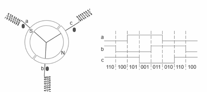
In a brushless motor, the position of the rotor is generally detected with three switching Hall devices. The Hall can be mounted 120° apart or 60° apart, we use the following example of a 3N2P motor with the Hall mounted 120° apart.

a, b and c are three Hall sensors. When the N pole is close to Hall a, a outputs a high level 1; when N is far from a, a outputs a low level. Similarly b and c have the same characteristics.
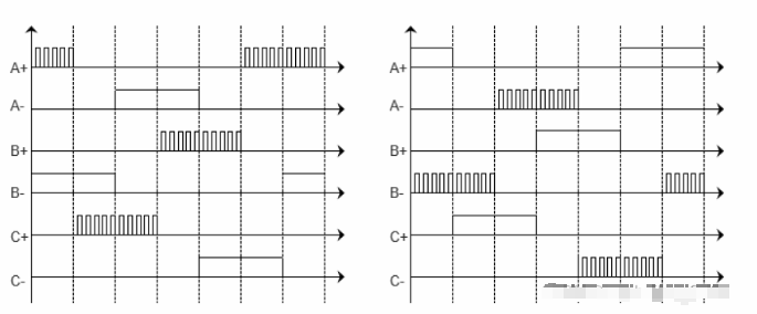
Because the rotor of the 2P is a pair of poles, the output waveforms of the a, b and c Hall will all change high and low levels once when the rotor is turned counterclockwise for one week, as shown in the following diagram.
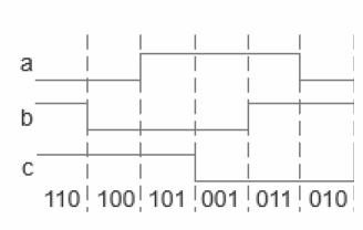
For example, in the diagram below, the current position of the rotor would cause the Hall output cba = 110:
This way we can determine the current position of the rotor from the output of the Hall sensor and, in combination with the method described in the previous article, we can make it rotate.
If we want to use the “two by two” method to make it turn counterclockwise, at position cba = 110 in the diagram, we should make coil B with a positive voltage and coil C with a negative voltage and coil A suspended; this state of charge is maintained until the N pole is turned close to position c, when the Hall output will automatically change to cba = 100, then our state of charge The A coil with positive voltage and the C coil with negative voltage and the B coil suspended, in order to allow the rotor to continue turning counterclockwise.
It is easy to see that the three Hall outputs are in six states in one cycle, which corresponds to the six states of the “two by two” method of energising the coils when the motor is rotating for one revolution.
So, we only need to use the outputs of the three Hall’s to control the energisation of the three ABC coils to control the continuous rotation of the motor.
Specifically, when turning counterclockwise, the following switches are made.

When turning clockwise, switch as follows:

At this point, brushless motor drives with Hall sensing can be driven up using the method described above.
There are many other methods for position detection with sensors, such as encoders, photoelectric sensors, resolvers and so on. A subsequent article will be dedicated to explain the small white white.
2) Sensorless (detection of counter-electromotive force) drive
In some micro and small motor systems, the installation of position sensors can have a detrimental effect on the size and cost of the motor, so sensorless position detection technology is also very practical. Let’s first explain its principle and then talk about its advantages and disadvantages.
We will use the following diagram as an example:
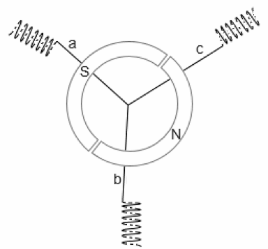
Compare the drive with the sensor in the previous section, in this position it is coil B with positive voltage coil C with negative voltage coil A suspended.
When the rotor magnet of the motor is rotating, there is obviously an induced electric potential generated in coil A. If, as the rotor magnet turns, the S pole approaches coil A and then moves away from coil A from the other side, the induced electromotive force in coil A will change from positive to negative (or from negative to positive), i.e. the induced electromotive force will have a crossing point. (Note that the zero crossing point of the induction potential is based on the central connection point of the three coils).

So, we can check the zero crossing point of the induction potential of the non-energised phase when the motor is turning, and we will know the position of the rotor.
There are various ways of detecting the over-zero point, and a comparator can be used, as shown in the following circuit, which is an example of detecting one of the phases.

Note the centre point voltage in the diagram, generally brushless motors do not lead out the centre point, it has to be obtained in other ways, you can get it by stringing resistors on the three phase lines and then connecting them together. The following diagram is a classic method of obtaining the centre point voltage, the left is the voltage taken on the three phase line, the right output is the centre point and the three phase over zero detection point.
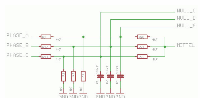
The resistor values in the diagram above can be adjusted according to the power supply and are mainly used for voltage division.
The capacitor in the diagram above is a simple filtering method, but it should be noted that adding capacitors to the filter will cause phase lag in the voltage, so the capacitor value should not be too large. If it is collected by software and then judged to be over zero, it can also be filtered by software.
The position of the rotor is detected and can be reversed accordingly, the optimum reversing position being 30° after the crossing point. So how do you know how long it takes to turn 30°?
The usual method, is to approximate that the rotor speed is uniform and that the time between the last phase change and the current crossing of zero is approximately equal to the time between this crossing of zero and the next phase change. From this, we simply use a microcontroller for timing to know the approximate 30° commutation position.
Another, simpler and more direct method, is to commutate immediately after the over-zero is detected. This method of commutation position is not optimal and some efficiency is lost, but it is the simplest to design.
At this point, the sensorless position detection and drive method, we have basically understood.
However, a new problem arises at this point. During the initial start-up, when the rotor is not yet rotating, there is no relative motion between the magnet and the coil, and no induced electric potential is generated in the coil, so how can the position of the rotor be determined? Let’s look at the next section, the problem of starting a sensorless motor.
3) Sensorless motor starting problems
As the sensorless mode requires the induction potential to determine the position of the rotor, when the motor is first started, or when the speed is very low, the induction potential is so small that it cannot be used to detect the position. This is why the starting of a sensorless brushless motor is a difficult problem.
The general approach is to use the three-stage method of starting, i.e. pre-positioning, then starting acceleration and finally entering closed-loop control. The specific implementation is as follows.
a) Pre-positioning
It is to first energise two phases for a short while, so that the rotor turns to a predetermined position; this energisation time, duty cycle needs to be determined according to the different motor and load conditions; otherwise it may burn out due to a long period of time on a coil, or the time is too short to predetermine the position.
b) Start acceleration
It is based on the direction of rotation, in turn to each phase of the power (phase change); start the process, the need for multiple phase change, and gradually accelerate; the same, this acceleration process is also related to the specific motor and load, need to test to determine, phase change frequency is too low, the motor acceleration is slow, the coil will also heat serious; phase change frequency is too high, the motor runs easily out of step, resulting in acceleration failure.
There are three common ways to accelerate: constant frequency boost method, constant voltage boost method, boost frequency boost method, the literal meaning can be understood, not to explain more; such as some model ESC, acceleration, each delay time than the last time to reduce 1/25, until the motor completely turn up.
c) Closed loop control
When the start acceleration to a certain speed, the counter-electromotive force and its over-zero point can be steadily detected, it can be switched to the closed-loop control state, that is, the phase change drive according to the control logic in the previous section.
As can be seen from the inductorless drive method, it is more complex to start, and also difficult to run when the induction potential is small at low speeds, so the inductorless brushless motor is not suitable for frequent start/stop and low speed operation, and is more suitable for volume and cost constraints and higher operating speeds.

4) Speed control of brushless motors
Through the above explanation, we know, whether inductive or non-inductive brushless motor, in the rotation, is to rely on the position of the rotor to determine the next moment of the power state, and the time to the next position is only related to the supply voltage, so, brushless motor speed control, the simplest way is to adjust the supply voltage, or use PWM control.
When using PWM control, the common method is to use one of the upper and lower bridge arms in the conduction interval, while the other half is controlled by PWM, as shown in the following diagram: the left diagram shows the way of PWM control of the upper and lower bridge arms, while the right diagram shows the way of PWM control of the lower and upper bridge arms:
Well, that’s it for the basics of brushless motors