What is the resonant circuit of LC and what are the functions of LC resonant circuit?
01 What is the resonant circuit of LC
An LC circuit is a circuit consisting of an inductor L and a capacitor C. There are mainly LC series resonant circuits and LC parallel resonant circuits. In amplifier circuits and other forms of signal processing, LC series resonant circuits and LC parallel resonant circuits are used extensively.
02 Role of LC resonant circuit
Frequency selector circuit: A frequency selector circuit is used to select the required frequency signal for amplification in a wide range of frequencies, which is often used in radio, television and sine wave oscillator circuits.
Absorption circuit: An absorption circuit is used to absorb, attenuate, or remove a frequency signal from a large number of frequencies.
Blocking circuit: A blocking circuit is formed to prevent a signal of a certain frequency from passing through an amplifier or other circuit in a large number of frequencies.
Phase-shifting circuit: A phase-shifting circuit that uses an LC parallel circuit to shift the phase of a signal.

03 Equivalent understanding method of LC resonance
The figure below shows a simple LC free resonant circuit in which L1 is an inductor and C1 is a capacitor.
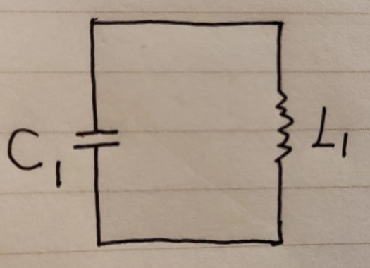
Figure 3.1 Free resonant circuit of LC
The resonance process of LC circuit is invisible and inaccessible, and it is quite inconvenient to understand, so we can use the left and right oscillation of a pendulum to simulate it. The pendulum schematic can be referred to the following figure.
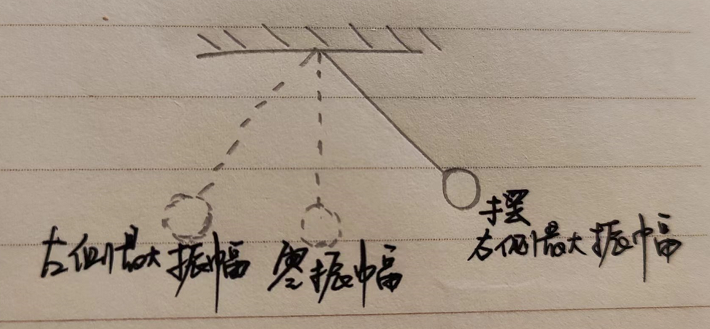
Figure 3.2 Schematic diagram of a pendulum
Illustration: After giving the pendulum an initial energy, the pendulum will swing from side to side. If the pendulum is not given a continuous force, the pendulum will swing with less and less amplitude due to external friction, and finally stop. Just like an LC circuit, if an LC free resonant circuit is given an initial energy, the circuit will resonate freely, and this free resonance will gradually decay to 0 if there is no continuous external supply of energy.
04 Electric-magnetic and magnetic-electric conversion processes in LC resonant circuits
Let’s look at the electric-magnetic conversion process first. Suppose that at the beginning, capacitor C1 is charged and electrical energy is stored in C1, and then the electrical energy of C1 is discharged to coil L1. In this process, the electrical energy in capacitor C1 is converted into magnetic energy in coil L1, and if the discharge of capacitor C1 ends, all the energy is stored in coil L1 in the form of magnetic energy.
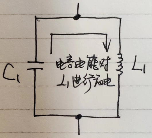
Figure 4.1 Electric-magnetic conversion process of LC resonant circuit
After capacitor C1 is discharged, the magnetic energy in coil L1 starts to charge capacitor C1 by generating current from the self-induced potential at both ends of the coil, and this charging process is the conversion of magnetic energy in coil L1 into electrical energy in capacitor C1.
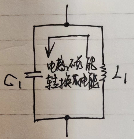
Figure 4.2 Magnetic-to-electric conversion process of LC resonant circuit
After capacitor C1 is charged, the voltage across capacitor C1 discharges L1 again, starting a new round of energy conversion.
05 Sine oscillation and decay oscillation of LC resonance
Assuming that there is no energy loss in capacitor C1 and inductor L1, the oscillation current in the resonant circuit is equal amplitude and sinusoidal.
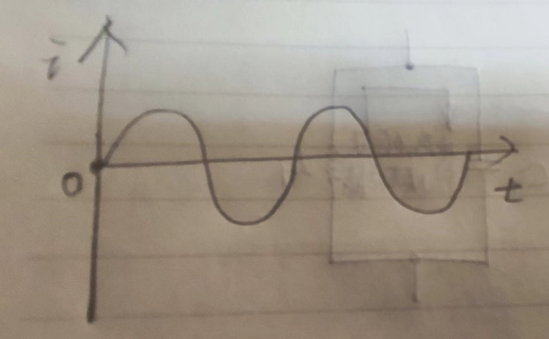
Figure 5.1 Schematic diagram of sinusoidal oscillation
If there are energy losses in the capacitor and inductor, the current in the resonant circuit is not equal in amplitude, but decays gradually.
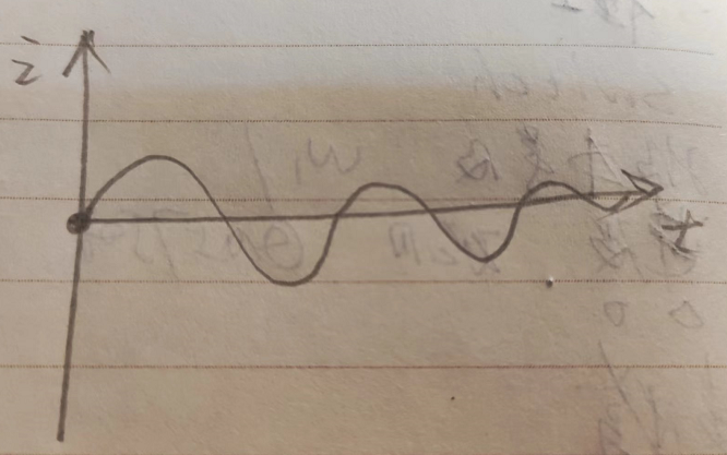
Figure 5.2 Schematic diagram of decay oscillation
06 Oscillation frequency of LC resonance
During the LC resonance, the capacitor C1 is constantly and repeatedly charged and discharged with a period called the oscillation period, which can also be described by the oscillation frequency. After the size of L1 and C1 is determined, the resonant frequency is determined, and we call this resonant frequency the intrinsic frequency or natural frequency. The resonant frequency f0 is the following equation.
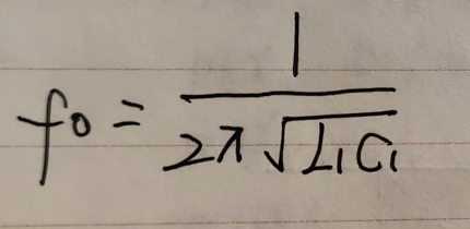
Whether the LC is a parallel resonant circuit or a series resonant circuit, the formula for calculating its resonant frequency is the same.