The connector degradation mechanism is very important to the connector performance and is critical to the performance assurance of the associated products. What is the degradation mechanism? What factors lead to connector failure? We will continue to explore this issue.

Connectors are used for the connection between two separable systems. Separability is necessary for a number of reasons, ranging from ease of manufacture to improved performance. However, when matched, connectors should not add any unnecessary resistance value between systems. Increasing the resistance value may cause system failure by distorting the signal or losing power. Connector degradation mechanisms are important because they are a potential source of increased resistance, and therefore, over time, lead to functional failure.
Let’s start with a brief review of connector resistance. Figure 1 illustrates a cross-section of a generic signal connector. The equations in Figure 1 represent the various sources of resistance within the connector. ro is the overall resistance of the connector and is the resistance between the conductor tail end point and the PCB connector footprint solder point. The two permanent connection resistances, Rp.c, are the resistances between the crimp connection points and the corresponding foot positions. Similarly, the two body resistances (Rbulk) are the rear contact body resistance and the parallel body resistance between the two posts of the connector; there is also a contact resistance at the interface or separation Rc. The overall connector resistance is the sum of the individual invariant connection resistances, the rear contact and lumen connector body resistance and the contact resistance at the separable, as all these resistances are connected in series.
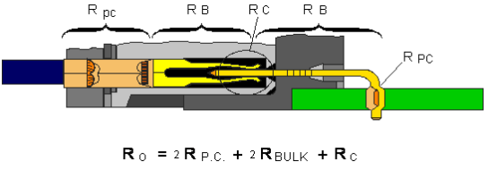
Figure 1, Schematic diagram of the connector resistance.
For the sake of discussion, let us assume that the measured total resistance value Ro is 15 milliohms. With this assumption in mind, let’s guess at the relative impact of the permanent connection resistance, the body resistance and the contact resistance at the separable on the overall connector resistance.
In this example, these values are the resistance values of a typical soft-shell connector, and the body resistance will account for most of the total resistance, close to 14 milliohms. The permanent connection resistance is a few hundred microohms, and the rest is the contact resistance at the separable point.
Although the body resistance of the connector contacts is the largest contributor to the connector resistance, it is also the most stable. The body resistance of an individual contact is determined by the material from which the contact is manufactured and its overall geometry. In this simple example, the resistance considering the length of the conductor can be calculated by the following company: Rcond. = r l/a.
In this equation, r is the resistivity of the conductor (which can also be the spring material in the connector), “l” is the length of the conductor, and “a” is the cross-sectional area of the conductor (or the geometry of the spring in the connector). For a given material, e.g. phosphor bronze and contact geometry, these parameters are constants and therefore the overall resistance of the connector is constant.
The permanent connection resistance and the interface or separable connection resistance are variable. These resistances are susceptible to a variety of degradation mechanisms, which will be discussed in a later article. It is important to note that connectors are subject to many effects such as harsh environments, heat, life, vibration, etc. And the total connector resistance may change from the original 15 milliohms to, for example, 100 milliohms, with the change in resistance occurring mainly in the separable and permanent connection resistances. The separable interface resistance is the most susceptible to degradation because of the forces and deformations that occur at the separable point, etc.
Simply put, the two main separable interfaces require certain forces and deformations to be generated. The connector bite force is the first and most obvious requirement. For high PIN count connectors, the bite force of individual PIN bits must be controlled, and the contact normal force is one of the main parameters governed by this requirement. For example, the contact force for a separable connection is in the tens to hundreds of grams, while the force in an insulated crimp connection, or IDC, is in the order of several kilograms, and the corresponding force in a pressed-in connection is the same. The high forces in this permanent connection provide greater mechanical stability and much lower resistance values than those of a separable connection.
In the same case, the higher permanent connection force allows for greater deformation of the contact surface relative to a separable connection. Crimp connections are the most obvious example of this, such as significant deformation of crimp terminals, as well as significant deformation of individual conductors. Both the force of the crimp connection and the corresponding PIN pin allow for greater deformation of the contact surface. As with the higher forces, the larger surface deformation of the permanent connections reduces their resistance compared to the separable contact resistance.
The deformation of the separable connection surface is also limited by another separable interface requirement: mating durability. High surface deformation usually leads to high surface wear, which in turn may lead to loss of contact coatings, such as gold or tin on the contact surface. This loss of coating will increase the corrosion susceptibility of the contact surface, which will be discussed in a later article.
The combination of detachable interface occlusion force and occlusion durability limits the deformation and mechanical stability of the detachable interface compared to a permanent connection and is responsible for the lower electrical stability of the detachable interface.
In general, the larger the contact area between two surfaces, the lower the resistance of the interface. In fact, for the resistance of the conductor length, the contact area between two surfaces is similar to the equation Rcond. = r l/a. Since separable connections have a lower contact area than permanent connections, they have a higher resistance.
In summary, the reduced force in separable connections leads to lower mechanical stability and the reduced contact area leads to higher resistance compared to permanent connections.
These issues, i.e., reduced contact force and reduced contact area, directly affect the degradation sensitivity of the separable contact interface. Figure 2 shows an enlarged schematic of the separable contact interface. The figure shows illustrates that at the microscopic scale of such a contact interface, all surfaces are rough. This means that the contact interface itself will consist of a distribution of contact points called a-points or dimples, rather than a complete area of contact. This uneven structure is responsible for the increased resistance of the contact interface. The reduced contact area, including the distribution of a-points over a geometric region, depends on the geometry of the contact surface. A type of resistance, called shrinkage resistance, results from current being squeezed to flow through a single a-point. The shrinkage resistance can be reduced by increasing the contact area by various methods, but it cannot be eliminated. Therefore, connectors will always add some resistance value to the electrical system. From this perspective, the primary goal of connector design is to control the magnitude and stability of the resistance.
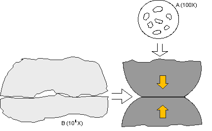
Figure 2: The inherent surface roughness of the contact interface from a microscopic point of view.
As mentioned earlier, the magnitude of the interface resistance depends on the contact area created when the plug and socket contacts come into contact with each other. There are two main factors that affect the stability of the contact resistance: disturbance of the contact interface and corrosion at the a-point. How these factors affect the connector degradation mechanism will be discussed later. In summary, these mechanisms include.
1 , corrosion occurs at and around the contact interface, thereby reducing the contact area. There are two corrosion mechanisms: surface corrosion, which directly affects the contact area; and induced or micro-motion, which can increase the susceptibility of the contact interface to corrosion.
2, loss of contact plating integrity due to inadequate plating or plating wear, which increases the susceptibility to corrosion. Most connector contacts are plated with a surface layer of a precious metal, such as gold; or a plain plated surface, typically tin. One of the primary purposes of these coatings is to protect the contact substrate (usually a copper alloy) from corrosion. The corrosion sensitivity of precious and non-precious metals is different and will be discussed separately later.
3, Loss of contact force, resulting in reduced mechanical stability and susceptibility of the contact interface to micro-movements. The main mechanisms leading to the reduction of contact force of connectors are excessive contact stress and stress relaxation. Stress relaxation is the loss of contact force with time due to time/temperature effects、