Today’s users expect great graphics from their mobile devices, but still need acceptable battery life. Other users of displays also expect low power consumption. These criteria obviously go in different directions, but there are available low-power microcontrollers that, if applied properly, can go a long way toward solving these problems. This paper will introduce three such devices, detailing three graphics-based applications.
The first application will look at using Silicon Labs’ EFM32 microcontroller to drive an electronic paper display. This paper will then describe two different approaches to driving LCDs using standard microcontrollers. In the first of these, a PIC32 microcontroller from Microchip will be part of the circuitry for developing a controllerless graphics embedded application. In the second, a standard ST62 microcontroller from STMicroelectronics will be used to drive the LCD. E-paper display

The growth of e-readers has created a demand for displays that look as if they are made of paper in order to create a more book-like experience for the reader. Such displays are reflective because they rely entirely on ambient light. There is no backlight. They are bistable and retain images even when power is lost. In addition to e-readers, they are used for industrial signage, electronic shelf labels, and other applications where image updates are infrequent. When displaying static images, they draw no current, thus extending battery life. However, they require a large amount of current to update the image, which can take one to two seconds.
A transparent capsule filled with dark oil constitutes the pixel. The oil contains negatively charged white titanium dioxide particles. The capsules have electrodes on the front and back of the capsule. If the front electrode is positively charged, the particles are attracted to it and the pixel appears white. If the back electrode is positively charged, the particles move in the direction that makes the black oil visible, so the pixels appear black. This is shown in Figure 1.
Figure 1: The electrodes attract negatively charged white particles to the front or back of the display to create an image.
Because they draw so little current, anything else in the display that draws current becomes relatively more noticeable, so the choice of microcontroller becomes important. In this example, we are using Silicon Labs’ EFM32 MCU because it can use its various energy modes to reduce the amount of current it consumes. In this type of application, it is primarily in energy mode 4, where it draws as low as 20 nA. MCUs in this range can have up to 1 MB of Flash and 128 KB of SRAM, which can be used to store frame buffers and images. These displays also take longer to update at low temperatures, but the MCU has an internal temperature sensor that can be used to adjust this time.
One problem with this type of display is the contrast ratio, which decays over time. Some manufacturers make claims about this rate of decay, and one example from one manufacturer was a specified drop in contrast from 9.1 to 7.1 in three weeks. ghosting can also cause problems where certain parts of the previous image can still be seen. This can happen if not all particles manage to move to the other side of the cell, resulting in gray shadows. This is usually solved by writing to the monitor multiple times for each image.
This example uses the Pervasive Displays SG020AS0T1 EPD expansion board and the Silicon Labs EFM32GG-STK3700
Starter Kit. The expansion board includes a flexible panel connector for display connection, 8 MB flash memory for image storage, temperature sensor, and a 20-pin connector for connection to the EFM32 MCU. The connector is available for 1.44, 2.0 and 2.7 inch paper display panels. The signal to drive the panel is routed on the 20-pin connector. The board comes with a 20-pin connector cable that is terminated in a standard jumper cable on the other side. Figure 2 shows how to connect the entry panel to the expansion kit.
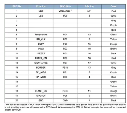
Figure 2: Connection table for connecting the expansion board to the Starter Kit.
Pervasive Displays’ panels are equipped with an integrated chip-on-glass (CoG) driver that controls the lines and columns on the panel; the CoG has a three-wire SPI interface to accept commands from the MCU. When writing images to the display, the panel requires a high voltage to drive the pixels. To achieve this without an external voltage supply, a charge pump circuit is used. the MCU must provide a PWM signal between 100 and 300 kHz to charge this voltage.
The process of drawing an image begins with the MCU powering up and initializing the CoG. During initialization, the MCU sends SPI commands to the CoG and must adhere to the timing sequence in the CoG documentation. It must also provide PWM waveforms as part of the initialization sequence. Image data is written multiple times to avoid ghosting and to improve contrast. The number of times a frame should be rewritten depends on the type and temperature of the display. Particles move more slowly at cooler temperatures, so the panel needs more rewrites. This is why the expansion board has a temperature sensor to help determine the necessary number of rewrites. there is also an internal temperature sensor in the EFM32 that can be used. The CoG driver is then closed, which must be done in a specific sequence according to the timing sequence that the MCU must follow. The sequence consists of first clearing the pixel registers and then discharging the charge pump capacitors.
The MCU needs to keep two frame buffers in memory, one for the new image and one for the old image still in the panel. This is because the panel is updated in four stages. First, the current image is inverted. Next, the entire panel is drawn white. Then, the reverse side of the new image is drawn, and finally the new image is drawn. After the power-off sequence is complete, the power to the panel can be removed and the image will remain in place.
In order to optimize power during display updates, the EFM32 must always be in the correct energy mode. Therefore, it should run at a high frequency when rendering new images. The clock frequency may slow down during the update phase, when frames are transferred to the panel via SPI, because that phase should run for a predefined amount of time. During the delay period, the MCU can be in sleep mode while it waits for the CoG to be ready. Depending on whether other tasks need to be performed during the sleep mode, it is wise to use Energy Mode IV as the sleep mode. When waking up from this mode, the MCU must perform a full reset and run boot and initialization code, which increases current consumption. Therefore, this mode is only fully beneficial when the sleep mode is long.
The main parameter that can be optimized to save power during the update is how long each phase should take. The display documentation should define reasonable defaults for each panel as well as temperature factors that can be used to extend this time to accommodate colder environments.
Controllerless graphical applications
Many embedded applications use internal or external graphics controllers, but these can add cost and complexity to the design. However, for basic GUIs, such controllers are usually not necessary. Instead, a microcontroller peripheral can be used to create a virtual graphics controller without taking up a lot of CPU time; the example given here uses less than 5 percent of CPU time. It uses Microchip’s PIC32 microcontroller and the company’s PICtail low-cost controllerless (LCC) graphics board, which can be used with many PIC32 starter kits.
Controllerless graphics systems need to send a frame of pixel information to the display glass at a refresh rate of about 60 Hz. This means that the system must constantly send frame data to the LCD panel, which takes up a lot of CPU time. However, the PIC32 MCU can have a direct memory access (DMA) peripheral that transfers data without CPU intervention, reducing CPU time to less than 5%.
In controllerless graphics applications, DMA should be set up to transfer frame data one line at a time through the parallel master port (PMP). Each line contains many pixels and the DMA sends a portion of the frame buffer during each transfer. a PMP or timer interrupt triggers the next DMA transfer until one line is transferred. For PIC32 devices with non-persistent interrupts, the timer is the DMA trigger source.
The PMP selects a read or write signal after each pixel transfer. the read/write selection of the PMP peripheral acts as the pixel clock for the display glass. After each line of pixel data is transferred, the CPU is interrupted by DMA and updates certain timing signals required by the LCD panel, such as HSYNC, VSYNC, and DEN. This process is repeated until the entire frame is drawn. The frames are stored in volatile memory, so the image can be dynamic. In this setup, SRAM is used. the system can be set to use internal or external SRAM as shown in Figure 3.

Figure 3: The system is set up to use external (top) and internal (bottom) memory.
The PMP data lines are used to map colors to the TFT LCD. 16 PMP data lines can be configured to transfer color data, depending on the color format used. In 8 BPP color mode, only 8 PMP data lines are required. When using external memory for the 16 BPP color mode, either 8 or 16 PMP lines can be used. With 8 data lines, the external memory data lines are still mapped to the TFT LCD in 16 BPP mode, but the PIC32 MCU is connected to the memory via 8 bits only. When a write needs to be performed, the MCU can use the low/high byte pins on the external memory to send the 16-bit color values to SRAM.
While the controllerless approach described here is intended for use with TFT LCD panels, it can also be used with CSTN or MSTN glass with only minor modifications. Most LCD panels can have 8 to 24 color data lines, depending on the color depth. These lines provide the raw color data to the LCD. The clock signals HSYNC, VSYNC, DEN and PCLK synchronize the pixel data with the graphics frame and the LCD panel. The sync line tells the LCD panel when data is at the beginning or end of a line (HSYNC) or frame (VSYNC). den (data enable line) lets the panel know when to send valid pixel data. den is required for TFT type panels because it takes time to set up the panel to get the correct pixel position.
The PCLK signal is the clock source for the entire system. A clock pulse from PCLK updates the panel. All other clock lines must be synchronized with the pixel clock to achieve proper image output. Not all display panels have HSYNC, VSYNC, and DEN lines. This example applies to panels that can be used to interpret each line and its purpose. However, panels that do not contain HSYNC and VSYNC signals can still be used with controllerless graphics setups.
The LCC software driver can help with synchronization that requires certain timing parameters, such as pulse width, leading and trailing edges of horizontal and vertical pulses. After compiling these values into the driver, the panel will display the frame.
Rendering new pixels in the screen is as important as refreshing the screen. This is done by the CPU writing to the display buffer. If frames are stored externally, DMA transfers are suspended while the frames are updated. This is because there is only one PMP peripheral, which is shared by the virtual graphics controller or the DMA transfer. This affects the refresh rate of the screen. The amount of pixel updates needs to be monitored to prevent the refresh rate from changing too much, otherwise the human eye will notice the change. This is done using a pixel count variable in the virtual graphics controller that is updated at each pixel write and cleared during each DMA interrupt.
Drive LCD with standard microcontroller
It is also possible to drive an LCD without a dedicated driver using STMicroelectronics’ ST62 microcontroller, which is suitable for applications that require a low-cost, small display but can take advantage of the microcontroller’s versatile capabilities.
The LCD is virtually transparent with a zero root mean square (RMS) voltage applied, and the LCD contrast (which makes the segments dark or opaque and therefore on) is caused by the difference between the applied RMS LCD voltage and the LCD threshold voltage, which is specific to each LCD type. The applied LCD voltage must alternately provide zero DC to ensure a long LCD life. The higher the multiplexing rate, the lower the contrast. The period of the signal must be short enough to avoid visible flicker of the display.
Each LCD segment is connected to an IO segment and a backplane that is common to all segments. The display using the S segment is driven by the S+1 MCU output line. The backplane is driven by a signal – com – controlled between 0 and VDD with a duty cycle of 50%. When the “ON” segment is selected, a signal with opposite polarity is sent to the corresponding segment pin. When the same signal com is sent to the segment pin, the segment is “off”. With the MCU, IO operates in the output mode of logic level 0 or 1.
For duplex drivers (see Figure 4), two backplanes are used instead of one. Each LCD pin is connected to two LCD segments, and each segment is connected to one of the two backplanes on the other side. Therefore, only (S/2)+2 MCU pins are needed to drive an LCD with S segments. three different voltage levels must be generated on the backplane: 0, V DD /2, and V DD. segment voltage levels are only 0 and V DD. LCD segments are invalid if the RMS voltage is below the LCD threshold voltage, and valid if the LCD RMS voltage is above the threshold voltage. Only the backplane voltage requires the intermediate voltage V DD/2. The ST62 IO pin selected as the backplane is set by software to 0 or VDD for the output mode V DD/2 level and high impedance input mode. This voltage V DD /2 is defined by two equal resistors connected externally to the IO pins. By using an MCU with a flexible IO pin configuration, only four additional resistors are required to implement a duplex LCD driver.
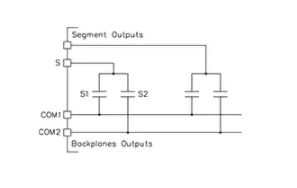
Figure 4: Basic LCD segment connection in duplex mode.
This approach is very cost effective for simple LCDs with 1 or 2 segments and multiplexing rates of up to 36 segments.
Conclusion
Many types of applications require some form of display, even those with cost and power pressures. This can cause headaches for many engineers who also face strict time-to-market constraints. However, as the three examples here show, standard low-cost and low-power MCUs can often be used to drive graphics applications.