Timer PWM output based on N32G45
PWM is a method of digitally encoding analog signal levels method. Through the use of a high-resolution counter, the duty cycle of a square wave is modulated to encode the level of a specific analog signal. The PWM signal is still digital because the full-amplitude DC supply is either fully available (ON) at any given moment. The PWM signal is still digital because the full-amplitude DC supply is either completely present (ON) or completely absent (OFF) at any given moment. The voltage or current source is applied to the analog load in a repetitive pulse sequence of ON or OFF. ON is when the DC supply is applied to the load, OFF is when the supply is disconnected. Any analog value can be encoded using PWM as long as the bandwidth is sufficient.

Pulse Width Modulation (PWM) is a very effective technique for controlling analog circuits using the digital output of a microprocessor, and is used in a wide range of applications from measurement and communication to power control and conversion.
One advantage of PWM is that the signals from the processor to the controlled system are in digital form, and then digital-to-analog conversion is performed. The effect of noise can be minimized (can be the same as a computer). Noise can only affect the digital signal if it is strong enough to change a logic 1 to a logic 0 or a logic 0 to a logic 1, too.
1.PWM mode
The user can use the PWM mode to generate a signal whose duty cycle is determined by the value of the TIMx_CCDATx register and whose frequency is determined by the value of the TIMx_AR register. And depending on the value of TIMx_CTRL1.CAMSEL, TIM can generate a PWM signal in Edge Aligned mode or in Center Aligned mode.
OCxMD=110 or set TIMx_CCMODx.OCxMD=111 to set PWM mode 1 or PWM mode 2. To enable the preload registers, the user must set the corresponding TIMx_CCMODx.OCxPEN. Then set TIMx_CTRL1.ARPEN to automatically reload the preload registers.
The user can set the polarity of the OCx by setting TIMx_CCEN.CCxP. When TIM is in PWM mode, the values of TIMx_CNT and TIMx_CCDATx are always compared with each other.
The preload register is transferred to the shadow register only when an update event occurs. Therefore, the user must reset all registers by setting TIMx_EVTGEN.UDGN before the counter starts counting.
1.1 PWM Central Alignment Mode
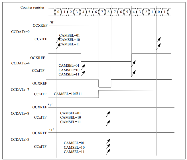
If the user sets TIMx_CTRL1.CAMSEL equal to 01, 10 or 11, the PWM central alignment mode will be activated. The setting of the compare flag depends on the value of TIMx_CTRL1.CAMSEL. There are 3 cases to set the compare flag, only when the counter is counting up, only when the counter is counting down, or when the counter is counting up and down. The user should not modify TIMx_CTRL1.DIR through software, it is updated by hardware.
An example of a centrally aligned PWM waveform is as follows, with the waveform set to TIMx_AR=8, PWM mode 1, and the compare flag set when the counter counts down corresponding to TIMx_CTRL1.CAMSEL=01.
The following matters should be noted by the user when using the central alignment mode.
The counter counts up or down depending on the value of TIMx_CTRL1.DIR. Be careful not to change both DIR and CAMSEL bits
The user should not write the counter in central alignment mode, as this may lead to unexpected results. Example.
If the value of the write counter is 0 or the value of TIMx_AR, the direction will be updated, but no update event will be generated
if the value of the write counter is greater than the value of the automatic reload, the direction will not be updated
For safety reasons, it is recommended that the user set TIMx_EVTGEN.UDGN before starting the counter to generate the update by software and not to write to the counter while it is running.
1.2 PWM Edge Alignment Mode
The Edge Alignment mode has two configurations, Count Up and Count Down.
Count Up
The user can set TIMx_CTRL1.DIR=0 to make the counter count up.
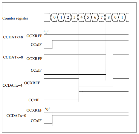
Example for PWM mode 1.
When TIMx_CNT < TIMx_CCDATx, OCxREF is high, otherwise it is low. If the comparison value in TIMx_CCDATx is greater than the auto-reload value, OCxREF will remain 1. On the contrary, if the comparison value is 0, OCxREF will remain 0. When TIMx_AR=8, the PWM waveform is as follows
Downward counting
The user can set TIMx_CTRL1.DIR=1 to make the counter count down.
Example for PWM mode 1.
When TIMx_CNT > TIMx_CCDATx, OCxREF is low, otherwise it is high. If the comparison value in TIMx_CCDATx is greater than the Auto Reload value, OCxREF will remain 1.
Note: If the nth PWM cycle CCDATx shadow register >= AR value, the shadow register value of the nth+1st PWM cycle CCDATx is 0. At the moment when the counter of the nth+1st PWM cycle is 0, no compare event is generated, although counter = CCDATx shadow register value = 0 and OCxREF = ‘0’.
- Example of breathing light output by PWM
- According to the N32G45 post introduction can be known LED hardware interface: https://bbs.elecfans.com/jishu_2320004_1_1.html

- Next I we take D2 and D3 as an example (D2 and D3 are just now on channel 1 and channel 2 of TIM3) to implement PWM output to control LEDs.
According to the reference manual chapter 7 can see, we want to achieve this function, we need to start TIM3 part of the remapping function.
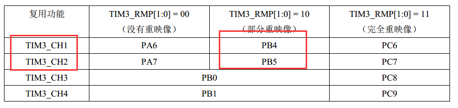
The partial remapping configuration for the TIM3 channel is as follows.
The register related introduction can be found in N32 user manual section 7.4 AFIO register configuration.
- Configure timer basic function and PWM mode.
When finishing PWM mode output, we need to finish the basic function configuration of timer first (turn on timer clock, set prescaler factor, set cycle time).
Timer related registers can be referred to N32 user manual chapter 12.4. A few common registers are listed below.
Control register 1 (TIM_CTRL1)
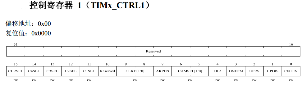
This register mainly implements the basic function configuration of the timer: setting the counting mode, starting the timer, etc.
Prescaler (TIM_PSC)
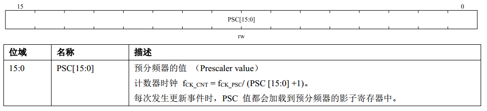
This register sets the operating frequency of the timer, for example, to achieve a counter +1 of 1us, the clock PSC=72-1.
Note: the timer’s clock line operating frequency is 72MHZ, i.e. CK_PSC=72MHZ
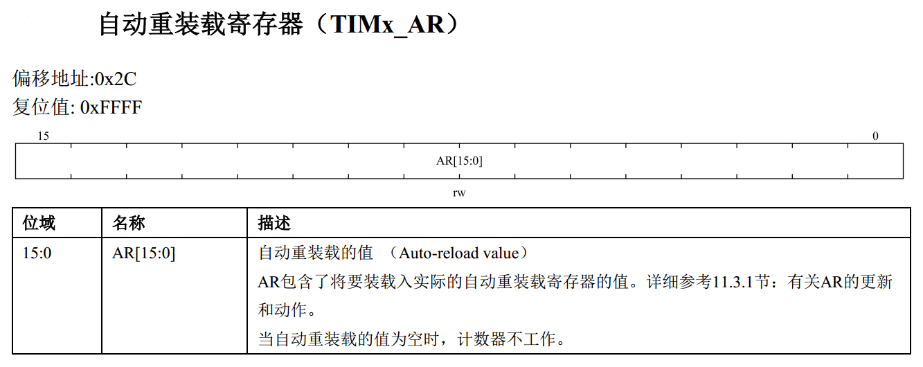
Reload register for implementing the timer count cycle.
Capture comparison register (TIM_CCDAT1)
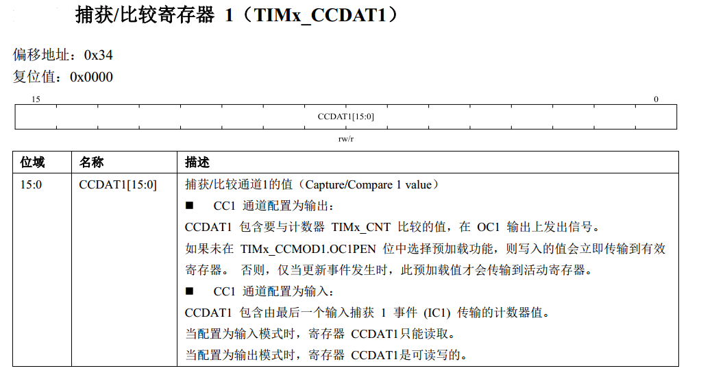
The CCDAT register is used to set the duty cycle when in output mode; when in input mode, CCDAT is used to save the captured level time.
Capture/compare register (TIM_CCMOD)
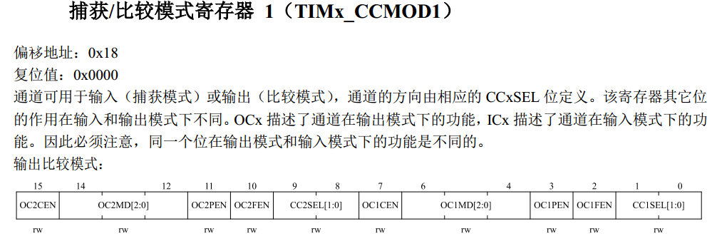
The capture/compare register is used to set the channel parameter information for the input capture mode and the output compare mode.
Capture/Compare Enable Register (TIM_CCEN)
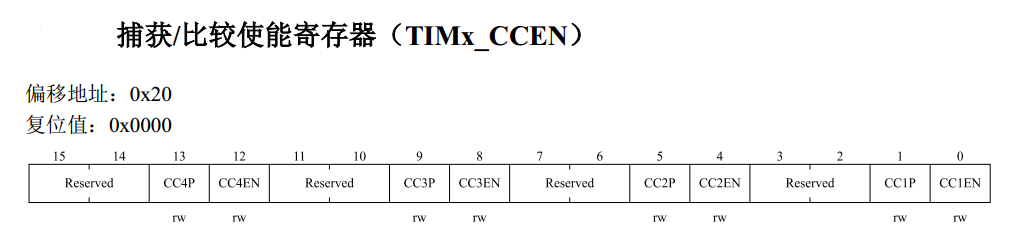
The Capture Compare Enable register is used to start the channel and set the active level polarity.
2.1 Timing configuration example
Complete the basic timer configuration, set the cycle time, set the dividing factor, configure the channel parameters, and output PWM.