Optical couplers (opticalcoupler, abbreviated as OC) are also known as opto-isolators or optical couplers, or optocouplers for short. The internal principle is shown in the following diagram.
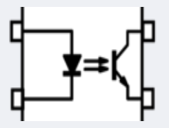
A simple illustration of the principle: by converting the transmitted signal into an optical signal via the light emitting diode on the left, and then converting the optical signal into an electrical signal by the photosensitive triode on the right. The ordinary optocoupler (low speed, non-linear; yes, that is, the cheapest kind) is explored here. The general optocoupler isolation voltage is about 6KV, which means that the resistance to static electricity (8KV and above) is not strong, and static electricity-related protection measures still need to be considered when using it.

Adjusting the pull-up and pull-down resistors of the optocoupler can adapt the current conversion rate (CTR) of the optocoupler to ensure that the signal transmission has a sufficient CTR ratio to ensure that the level of the triode side can be pulled to the bottom. On this basis we look at the delay of the signal transmission by the front and rear matching resistors.
*CTR: The ratio (in percentage) of the maximum current flowing on the triode side to the diode conduction current when the optocoupler diode is on.
The following is the most basic (and least expensiveヽ( ̄▽ ̄)و) circuit for communication using optocouplers.
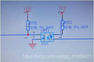
As can be seen in the photocoupler shown above, the pull-up resistor used on the input and output sides is 510Ω, which is a suitable resistance value for communication using this photocoupler. However, there is a problem with using the circuit shown above, as shown in the following diagram.
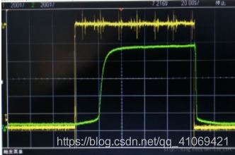
The yellow is the input waveform and the green is the output waveform. Yes, the output waveform is delayed by 20us relative to the input in terms of timing, which is fine in scenarios where the signal requirements are not high. However, for communication rates greater than 9600bps, the signal integrity is affected. The reason for this is that the optocoupler’s internal
The triode inside the optocoupler is equivalent to a capacitor, and the pull-up resistor forms an RC circuit. This delay is due to the charging effect of the RC (or is used to activate the triode inside the optocoupler). As shown in the diagram above, a signal of 100us becomes a signal of approximately 80us after the optocoupler, which is worth considering, especially if the
The rate of the signal is further increased, especially in the embedded field where MCUs have a certain time requirement for high level signal acquisition. By varying the resistance at the front and rear of the optocoupler and then measuring the output delay time, the following conclusions* are drawn.
Within a certain range (without burning out the optocoupler), increasing the resistance on the diode side of the optocoupler or decreasing the pull-up resistance on the triode side can reduce the delay of the output waveform.
Is there any other way to free the common optocoupler from the pull-up resistor and pull-down resistor?
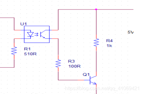
Yes, the diagram below shows that the pull-up resistor can be reduced to about 100Ω by using an optocoupler to control the on/off of the triode, which basically guarantees a 2us delay in communication.
A delay of 2us is basically close to the state of a high-speed optocoupler.