The IO port of the microcontroller has a certain load carrying capacity. But the current is very small, the driving capacity is limited, generally within 10-20mA. So generally do not use the microcontroller directly drive the load this way.
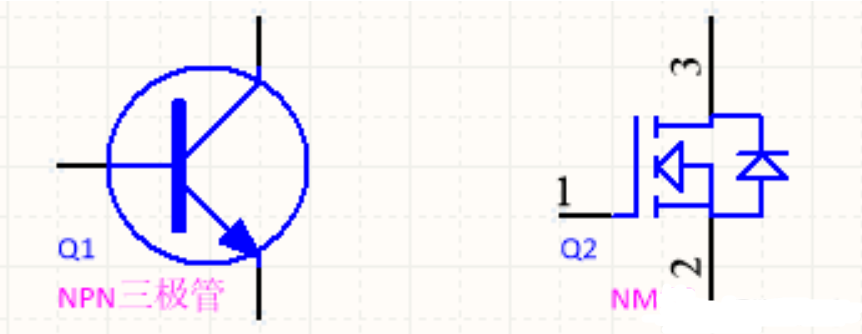
- As for the microcontroller why the general choice of transistors rather than MOS tubes? Need to understand the difference between transistors and MOS tubes, as follows.
① transistors are current-controlled, transistor base drive voltage as long as it is higher than Ube (generally 0.7V) will be able to conduct.
② MOS tube is a voltage-controlled, the drive voltage must be higher than the threshold voltage Vgs (TH) in order to conduct properly, different MOS tube threshold voltage is not the same, generally about 3-5V, the saturation drive voltage can be in 6-8V.
The processor is generally concerned about low power consumption, and the power supply voltage is getting lower and lower, generally the microcontroller power supply is 3.3V, so its maximum I/O voltage is also 3.3V.
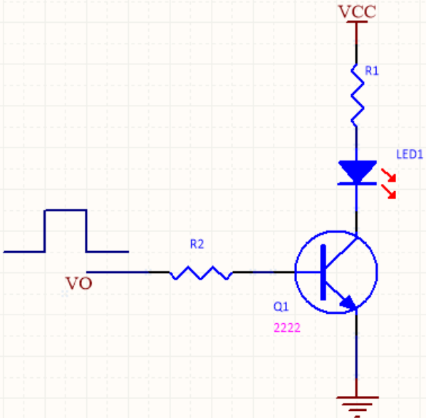
① Direct drive triode
3.3V voltage is definitely greater than Ube, so directly in series with a suitable resistor at the base, so that the transistor work in the saturation area can be. Ib = (VO-0.7V)/R2.

② Drive MOS tube
Through the previous also learned that the saturation voltage of the MOS tube > 3.3V, if 3.3V to drive, it is likely that the MOS tube simply can not open, or in a semi-conducting state.
In the semi-conducting state, the tube’s internal resistance is very large, driving a small current load can be so used. But the high current load will not work, the internal resistance is large, the tube power consumption, MOS tube is easy to burn out.
Therefore, the general choice of I/O port directly control the transistor, and then control the MOS tube.
When I/O is high, the triode conducts, the MOS tube gate is pulled low, and the load RL does not work.
When the I/O is low, the triode does not conduct, the MOS tube divides the voltage through resistors R3 and R4 to provide a suitable threshold voltage for the gate, the MOS tube conducts, and the load RL works normally.