Practice shows that the circuit mechanical switch on the inductive load switching, often on the circuit of other electrical and electronic equipment interference, after research, this interference is characterized by pulse swarms, pulse repetition frequency is high, the rise time of the pulse waveform is short, but the energy of a single pulse is small, generally will not cause equipment failure, but make the equipment generated by the misoperation is often visible. The reason why pulse swarm interference can cause equipment malfunction is because the pulse swarm charges the junction capacitance of semiconductor devices in the line, and when the energy on the junction capacitance accumulates to a certain level, it will cause equipment malfunction.
The standard simulates the interference caused by mechanical open-hanging on inductive load switching in the power grid, which can complete the assessment of electrical and electronic equipment in terms of resistance to electrical fast transient pulse group performance.
Pulse group interference is added between the power line and ground, so the essence of the test is a common mode test.
Test standard for pulse swarm
EFT immunity is a pulse group consisting of many fast transient pulses coupled to the power port, signal and control ports of electrical and electronic equipment and observe the degree of maintenance of the original performance of the equipment under test when subjected to these pulse disturbances. The purpose of the test is to test the performance of electronic and electrical equipment when subjected to such transient disturbances. Through the test of electrical and electronic equipment in the repetitive rapid transient pulse group interference performance evaluation.

Introduction of pulse group generator and test environment


Basic lines and output waveforms of pulse group generators
Power line coupling / decoupling network
The network line provides the ability to apply the test voltage to the power port of the test equipment under asymmetric conditions, where the so-called asymmetric interference refers to the interference between the line and the earth.
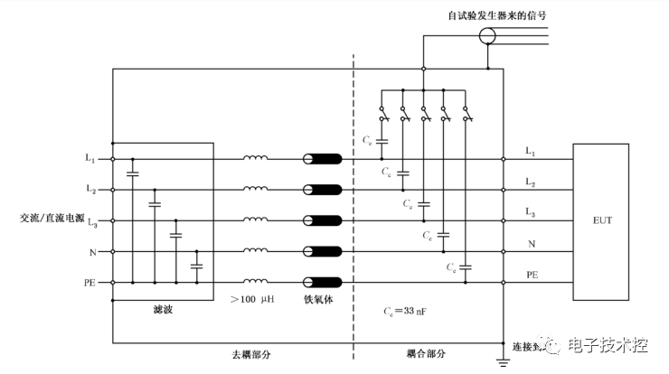
Power line coupling/decoupling network line
Capacitive coupling clips
The coupling clip can couple the fast transient pulse group to the test line without any electrical connection at the terminals of each port of the test equipment, the cable shield or any other part of the test equipment. The cable of the line under test (signal line) is placed between the upper and lower coupling plates of the coupling clip, and the clip itself should be closed as much as possible to provide the maximum coupling capacitance between the cable and the coupling clip. The interference applied through the coupling clip is still common mode in nature.
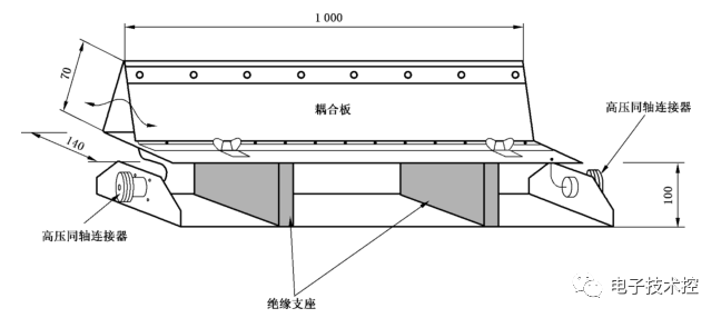
Structure of capacitive coupling clip
Design of pulse group protection for products
① Pulse group immunity test is one of the more difficult to pass among all immunity tests, and it is also one of the tests with poor repeatability and comparability.

② The pulse group immunity test is an anti-common mode interference test, which determines that effective measures for common mode interference must be used when dealing with interference. For example: the X capacitor of the power inlet is no suppression of EFT interference, if the equipment is a metal shell, Y capacitor will work to bypass the high-frequency EFT to the top of the shell, and then back to the signal source through the distributed capacitance between the equipment shell and the reference ground, so as not to enter the circuit.
③ EFT interference in the transmission process, partly through the transmission line into the test equipment (conducted emission); partly to spill out from the line and become radiation signal into the test equipment (radiation emission). Therefore, the interference to the test equipment is actually a combination of conduction and radiation. The ratio of conduction and radiation and the length of the power line, the shorter the line, the more conduction components, while the smaller the proportion of radiation; conversely, the proportion of radiation is large. This is exactly the same conditions, why the metal casing of the equipment to be easier than non-metal casing equipment through the test of reason, because the metal casing of the equipment to resist radiation interference ability is stronger.
④ pulse group interference conductive amount accounted for most of the controllable and considerable, so for pulse group interference, the most common suppression methods are mainly used to filter (power line and signal line filtering) and absorption (ferrite core to absorb). Among them, the use of ferrite cores to absorb the program is very cheap and very effective. The amount of radiation can be minimized by changing the location of the transmission cable or increase the shielding, radiation control and observability is very poor, only under the same conditions for comparative testing.