Preface
CRT (Cathode Rays Tube) is the most primitive electronic display technology and has been widely used in analog television systems in the last century. In this paper, we will introduce the principle, characteristics and some key terms of CRT display technology in the context of analog television system.

As we all know, CRT display has been gradually replaced by digital display, has withdrawn from the stage of history, the reason why this paper introduces it, there are three reasons.
(1) analog TV is our generation’s childhood memories, beautiful and mysterious. Now look back and find that the technology is so simple, interesting and worth talking about.
2) Help understand display timings (video mode, or display timings). For those who have written display drivers, the long list of timing-related parameters (xres, yres, hsync len, vsync len, left margin, etc.) of the display is enough to break yourself. Tracing back to their roots, they arose from CRT technology, and now the reason why they still exist is largely a continuation of CRT, without much substance.
(3) Now many cutting-edge display technologies, such as PDP, FED, etc., are similar to the working mechanism of CRT (for details, please refer to the introduction in “Introduction to Display Technology (2)_The Past and Present of Electronic Display”). Understanding the CRT is the basis for understanding these new technologies.
Introduction to CRT
The essence of CRT display technology is.
1) An electron gun emits an electron beam and accelerates it under the action of an accelerating electric field.
(2) The electron beam bombards the fluorescent material to emit light. The brightness of the luminescence depends on the speed of the electron beam, i.e. the strength of the accelerating electric field.
(3) The intensity of the accelerating electric field is controlled by the input video signal, so the video can be restored.
(4) The electron beam can produce a light spot with a diameter of slightly less than 1mm, and under the control of the deflection system, it can light up all the areas on the screen in time and produce a finished picture (as seen by the human eye) by using the principle of visual transience of the human eye.
Therefore, the CRT contains the basic components such as electron beam generation (electron gun), acceleration system, deflection system, and display screen coated with fluorescent substances, which are combined together with a tube housing, which is often referred to as a cathode ray tube (CRT).
Introduction to analog TV system
The analog TV system is a system containing video signal acquisition and output, encoding, transmission, decoding, and restoration display, and its block diagram is as follows.
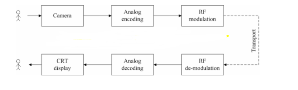
Picture 1 Analog TV system
The display terminal (TV) in analog TV system basically uses CRT display, so it is also called CRT TV. In general, CRT TV as a whole contains three parts: RF de-modulation, Analog decoding, and CRT display.
Photoelectric conversion and electro-optical conversion
CRT is a technology that converts electrical signals into optical signals, but where do the electrical signals come from? Coincidentally, a similar technique can be used, as follows.
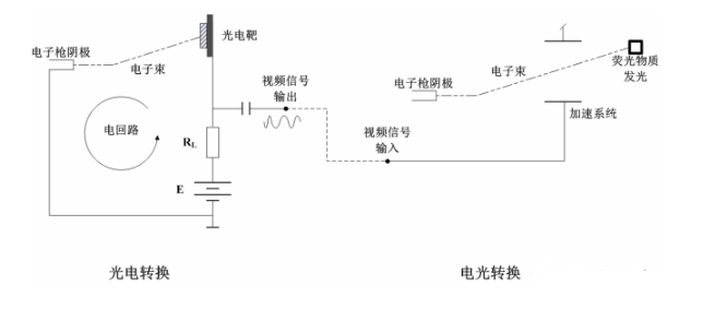
Image 2 Photoelectric & electro-optical conversion
The above diagram depicts the technical basis of the CRT-based analog TV system.
An electronic photoelectric target forms an electrical circuit to convert the light signal into an electrical signal, completing the photoelectric conversion.
The accelerated electron fluorescent substance emits light, converting the electric signal back to the light signal and completing the electro-optical conversion.
The purpose of photoelectric conversion is to convert the image signal to electrical signal for transmission and preservation, and the converted electrical signal is the source data for electronic display. The left part of the above figure describes the photoelectric conversion process based on cathode ray.
1) The cathode of the electron gun generates an electron beam and hits a conductive photoelectric target.
(2) photoelectric target through a resistor (RL) and the anode of the electron gun connected, hit on the photoelectric target of the electron beam flow through the resistor back to the anode of the electron gun, thus forming an electrical circuit.
(3) the photoelectric target itself also has resistance, and with the change of light intensity and change (can be seen as a photoresistor). Therefore, between the photoelectric target and RL will produce a voltage output that changes with the light, which is the video signal output.
After the conversion of light signal to electrical signal, after storage, transmission, conversion, will be in the form of input signal, control the intensity of the accelerated electric field in the CRT, and then control the luminous intensity of the fluorescent material on the fluorescent screen, to complete the electro-optical conversion (electronic display).
After understanding the above photoelectric conversion and electro-optical conversion process, we will have the following questions.
Question 1: A photoelectric target can only reflect the light change of one point, but this is obviously not enough, a large enough plane on all points of the light change to be meaningful, how to do?
Question 2: Why must we need an electron beam to form an electrical circuit, a simple wire can also achieve the purpose?
To answer the above two questions, we need to further understand the principle of electron scanning.
Electronic scanning
First of all, to answer question two, electron beam is certainly not necessary, now commonly used digital camera, digital display and other technologies, do not need the involvement of electron beam, of course, they are not in the scope of this article, will not be too much involved. Therefore, let’s analyze the electron beam based scenarios first.
For question one, how to get the light variation of multiple points on a plane? The resourceful engineers came up with Scanning. By scanning, we mean that only one point is processed at the same moment. If all the points can be processed in a short time (enough time to deceive the human eye, e.g. 40ms), everything will be fine, as shown in the following figure.
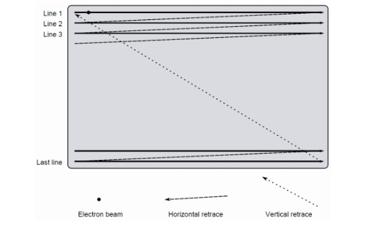
Image 3 Raster scanning
The electronic scanning (also called raster scanning, Raster scanning [2]) depicted in the picture above is used in analog TV systems for both image acquisition and image display. It can be understood as follows.
We can use multiple photoelectric targets (suppose MxN of them) to form a plane, and then add a suitable magnetic field in the horizontal and vertical directions of the path through which the electron beam passes. The strength of the magnetic field is determined by a coil (deflection coil) controlled by a sawtooth wave signal, and since the magnetic field deflects the electron beam, it is possible to control the beam to hit each photoelectric in a left-to-right and top-to-bottom manner, respectively. target. This process is called scanning.
As a result of scanning, the optical signals represented by the MxN photoelectric targets are converted into electrical signals and output in turn. Such a sequence of electrical signals, called an image frame (Frame), the receiver (CRT display), according to the same rules, can be restored to display such an image frame.
About electronic scanning, there are many important concepts that will be used in the writing of the driver related to the display, which are explained below in combination with the picture above.
(1) Scan lines (Scan lines) and resolution (Resolution)
For electronic scanning (here image acquisition is an example), the signal output from all the photoelectric targets in a row is actually a continuous signal, which means that
The number of photoelectric targets contained in a row is not important for scanning (or displaying), it only affects the accuracy of the optical signal acquisition, i.e. the fineness of the image. Even the display side does not care how many photoelectric targets are used on the acquisition side (since it is analog, it has no way to know). This feature determines that in the horizontal direction of the electronic scan, there is no concept of resolution, the entire horizontal direction of a line, called a scan line (Scan line).
For the analog CRT display, it is only necessary to map a line of analog signals over according to the characteristics of the display (how long the horizontal direction is).
At the end of each scan line, the electron beam needs to return to the starting point of the next line under the deflection of the horizontal and vertical deflection fields (this process is called back-scan, which will be described below), and no signal acquisition is allowed in between, thus each scan line is discontinuous. In other words, the electronic scan has the concept of resolution in the vertical direction, i.e., how many scan lines (Scan lines).
In summary, in electronic scanning, the resolution can be expressed in Scan lines, for example, 576 lines.
2)Back sweep (Horizontal/Vertical retrace)
After scanning a line from left to right, the electron beam needs to move back to the far left under the horizontal deflection field and deflect down one scan line under the vertical deflection field in order to scan the next line. Similarly, after scanning a frame from top to bottom, the electron beam also needs to move back to the leftmost side under the action of the vertical deflection field. Thus, the horizontal and vertical deflection fields are, in effect, a periodic sawtooth wave, as follows.
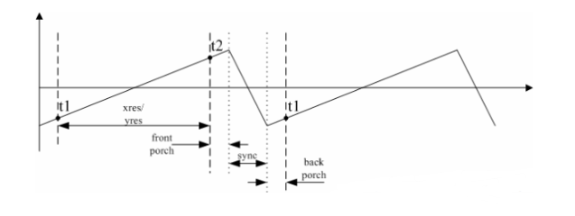
Image 4 Scanning-pattern
A rising period with a positive slope is called a forward scan, and the beam will be deflected from left to right (or up and down). A negative slope down period, called a retrace, deflects the beam from right to left (or down and up).
Since no signal can be acquired (or output) during the retrace, the beam is turned off, called a blank (Horizontal/Vertical balnk). After the sweep is complete (back to the far left or far right), the electron beam needs to be turned back on, called unblank.
Note 1: Students who understand display drivers (such as linux framebuffer) should not be unfamiliar with blank/unblank, which is where they come from.
3)Front porch and back porch
As can be seen from the above description, the blank operation is required at the beginning of the back scan, i.e., to turn off the emission of the electron beam. In the world of analog electrons, turning off the emission of the electron beam is really a matter of dropping the voltage that excites the emission of the electron beam from a high level to a lower level (close to zero), but the drop takes time (for a variety of reasons that will not be analyzed in detail here), thus.
The back-scan cannot start until the level drops to a safe value (the electron beam is no longer emitting).
In other words, the effective video signal must end before the start of the back-scan (i.e., “t2” in picture 4 above), and the period from the end of the effective video signal to the start of the back-scan, called the front porch, is also the time required for blank operation.
In addition, back to the sweep also takes time (do not entangle the reason, are old history), this period can be used as a synchronization signal.
By the same token, when the unblank operation is completed after the back sweep, the level rises from near zero to the normal value (where the electron beam can be emitted, “t1” in picture 4), which also takes a certain amount of time, called the back porch. During this period of time in the back porch, the video signal is also invalid.
To sum up: the effective range of the video signal is the range from t1 to t2 in picture 4, which is generally called xres/yres; the invalid range of the video signal is the range from t2 to t1 in picture 4, including front porch, sync len and back porch (horizontally or vertically), which is generally called blanking interval ( Horizontal/ Vertical blanking interval [3],[4]).
(4) synchronous signal (sync pulse)
As can be seen from the description of “Picture 1 Analog TV System”, the video signal needs to go through Analog encoding before it is sent, and the encoding process does not include front/back porch information because the value of the front/back porch is related to the circuitry of the specific system and therefore should not be included in the in the transmission system.
However, from the time axis, the video signal is discontinuous, with a horizontal blanking interval after each line of valid signal and a vertical blanking interval after each frame of valid signal. the encoder uses these blanking times to pass a special signal, the synchronization signal (HSYNC and VSYNC, in analog systems this signal is pulsed at a higher level than the normal video level) to inform the receiver of the start and end of each line and frame of the video signal. 6.
- display timings and videomode
After the introduction of the above chapter, we have a basic understanding of CRT display technology, and lead to the concepts of front and back shoulder, synchronization signal, etc. At this point, we can go back to the linux kernel and look at the definition of several data structures.
| 1: /* include/video/display_timing.h */ |
| 2: |
| 3: struct display_timing { |
| 4: struct timing_entry pixelclock |
| 5: |
| 6: struct timing_entry hactive; /* hor. active video * |
| 7: struct timing_entry hfront_porch; /* hor. front porch */ |
| 8: struct timing_entry hback_porch; /* hor. back porch */ |
| 9: struct timing_entry hsync_len; /* hor. sync len */ |
| 10: |
| 11: struct timing_entry vactive; /* ver. active video * |
| 12: struct timing_entry vfront_porch; /* ver. front porch */ |
| 13: struct timing_entry vback_porch; /* ver. back porch */ |
| 14: struct timing_entry vsync_len; /* ver. sync len */ |
| 15: |
| 16: enum display_flags flags; /* display flags */ |
| 17: }; |
hactive, hfront_porch, hback_porch, hsync_len/vactive, vfront_porch, vback_porch, vsync_len, Is it no longer strange?
Look at struct videmode and struct fb_videomode, as well as the fbset command under linux (I won’t post the code, please refer to include/video/videomode.h, include/linux/fb.h and Documentation/fb/ framebuffer.txt), are similar and no longer difficult to understand.
Summary
Finally, the introduction of CRT and analog TV systems in this paper is just a hair, many of the more detailed content, such as frame rate, interlaced scan (Interlaced scan), coding, display system (PAL/NTSC), etc., are not involved. For the sake of space and personal energy, we will not introduce them one by one, if you are interested, you can refer to some links at the back of this article.