In this project, we will control the speed of DC motor wirelessly using IR or TV remote control. Here, we are not going to use any microcontroller. We are using basic components and 555 timer IC for this task. The circuit can control 5 different levels of DC motor speed and any IR remote control (like TV/DVD remote etc.) can be used to control it.

Required components.
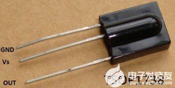
TSOP1738 -1Nos.
555 Timer IC -2Nos
CD4017 -1No
BC547 Transistor -1No
12-0-12 Transformer -1 No.
1n4007 Diode -10Nos.
Capacitor 1000uF, 1uF, 4.7uF, 0.01uF – 1 each
0.1uF Cap – No. 4
Resistor 10k-2Nos.
Resistor 1k-3 No
220K Resistor 220k, 30k, 22k, 15k, 3.3k, 220, 650 Ohm – 1 ea
330 Ohm Resistor 330 Ohm -3 No
Light Emitting Diode
Circuit diagram and working schematic.
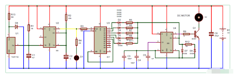
The motor speed control circuit is a bit complicated for beginners, but in general it is easy. In this case, we have the TSOP1738 IR receiver U1, which is responsible for detecting the TV remote IR signal. Once it gets the signal from the TV remote, it triggers the 555 monostable multi-harmonic oscillator U2. This multi-harmonic oscillator is used to generate a single pulse each time any button on the IR remote is pressed.
Typically, the TV IR remote control sends 38KHz modulated pulses and the TSOP1738 detects the IR radiation modulated to 38Khz. The output of the TSOP is active low, which means its output stays high when there is no IR and goes low when IR radiation is detected. It has three pins, ground, Vs (power) and output pin. So whenever we press any button on the IR remote, it triggers the monostable 555 timer (U2) by sending a low pulse to its trigger pin 2.
In addition, the 555 timer sends clock pulses to decimal counter IC 4017 to transfer its output to the next output pin. 4017 decimal counter IC is used to change the timing resistor value of the second 555 timer IC (U4), which is configured for non-stationary multi-tuned oscillator mode. This 555 IC is used to generate the PWM signal. Decimal Counter 4017 sets the resistor at both ends of the U4 non-stationary multi-tuned oscillator by switching the output to the next output pin. By changing the value of this timing resistor, the duty cycle of the PWM signal changes, so that the speed of the DC motor changes each time we press the IR remote control button.
The 4017 IC is a CMOS decimal counter chip. It can generate outputs on 10 pins (Q0 – Q9) sequentially, which means it can generate outputs on each of the 10 output pins. The output is shifted to the pin by a low-to-high clock pulse at pin 14 (positive edge trigger). First, the output at Q0 (pin 3) goes high, and then with each clock pulse, the output advances to the next pin. Just like one clock pulse makes Q0 low and Q1 high, then the next clock pulse makes Q1 low and Q2 high, and so on. After Q9, it will start from Q0 again.
There are five selective resistors (R5, R6, R7, R8, R11) which are responsible for generating five different PWMs on the output pins of the 555 IC (U4).In this circuit, we have used a 12v dc supply throughout the circuit. Here, we have placed a 4.7v Zener diode to protect the TSOP1738. the DC motor used here is a 12v DC geared motor driven with the help of a BC547 NPN transistor.