This paper describes in detail the design of an embedded Internet terminal implemented with the MSP430 microcontroller from TI, including both hardware and software components. The application interface allows to create new tasks or change existing ones, and to communicate with other terminals in the Internet. In this paper, a hardware schematic is given to illustrate the workflow of some of the modules.
- Introduction
- The role of computer communication systems, especially the Internet, is becoming increasingly important in daily life and is on an accelerating trend. Nowadays, Internet access is no longer the exclusive domain of personal computers and network workstations, but many embedded systems controlled by microcontrollers (or microcontrollers) have also become part of the Internet network nodes, and usually, such embedded systems can be called embedded Internet terminals. Imagine, if through the web browser, can complete the micro-controller control of the remote, and can receive the signal collected by the micro-controller, that will bring great convenience to people’s lives and greatly promote the development of productivity. For example, if through the office of a computer connected to the Internet and installed in the home embedded controller, people can learn about everything that happens at home or, then a series of problems such as home security will wait for a good solution.

MSP430 is due to TI (Texas Instruments, Texas Instruments) developed 16-bit microprocessor, its outstanding feature is the emphasis on low power consumption, very suitable for a variety of low power requirements of the application, there are several series and models. Because of its high cost performance, it is widely used in many fields such as home automation, medical devices, security systems, building control systems, etc. MSP430F149 used in this Internet terminal design program is a member of the MSP430F1X added by TI in 2000.
- protocol basis
ISO (Internet Standard OrganizaTIon, International Standards Organization) in 1981 proposed OSI (Open System Interconnect, Open System Interconnection) seven-layer network model. The greatest advantage of the seven-layer network model is that it clearly distinguishes between the concepts of services, interfaces, and protocols: services describe what functions a layer provides to the upper layer, interfaces describe how the upper layer uses the services of the lower layer, and protocols deal with how to implement the services of this layer.
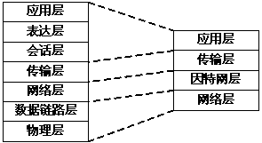
The four-layer network model used in the Internet is a subset of the OSI seven-layer network model with four specific layers: the application layer, the transport layer, the Internet layer and the network layer. Figure 1 shows the correspondence between the four-layer network model of the Internet and the OSI seven-layer network model. The Internet model ensures that all transmitted data can be reconstructed in the normal order at the remote end through sequence numbers in the data segment (Segment), and the integrity of data transmission is ensured through acknowledgement.
orrespondence between the four-layer network model of the Internet and the OSI seven-layer network model. The Internet model ensures that all transmitted data can be reconstructed in the normal order at the remote end through sequence numbers in the data segment (Segment), and the integrity of data transmission is ensured through acknowledgement.
Figure 1 Correspondence between the OSI seven-layer protocol and the four-layer model of the Internet
2.1 Ethernet (Ethernet) [1]
Ethernet is the most widely used type of LAN today, and it belongs to the network layer among the four-layer network model of the Internet. Each node in an Ethernet network has the same access rights to the network, and network occupancy between them is achieved by means of carrier listening multiple access ( CSMA/CD ) with conflict detection. Data is encoded using Manchester encoding, and connections in the network are typically made using twisted pair or coaxial cable. Each node in Ethernet has a 48-bit, uniquely numbered address. The maximum length of each data frame is 1518 bytes, with the first 48 bits being the destination address, the second 48 bits being the data source address, followed by a 2-byte data frame type value, and at the end of the data frame, a 4-byte cyclic redundancy code check (CRC) value is automatically generated to ensure the integrity of the data frame.
2.2 Transmission Control Protocol (TCP)
TCP provides a reliable data flow service, and although TCP is a member of the DARAP protocol group, it has a great deal of independence. It is very popular because it has only minimal requirements for lower layer network protocols and can be easily built on different networks, and the ISO/OSI Transport Layer Standard Class IV TP-4 was built on TCP as a prototype. TCP can work on a wide range of networks and can provide virtual circuit services and stream-oriented transport services. User data can be transmitted in an orderly and reliable manner. The TCP service provides a reliable inter-process communication mechanism in case a packet can be lost, corrupted, duplicated, delayed or out of order, and the protocol can automatically correct errors.
2.3 Internet Protocol (IP)
The most important protocol at layer 3 is IP, which links multiple networks into an interconnected network. ip works by linking more than one message processing network into an inter-network. the basic task of IP is to transmit datagrams over the inter-network, and individual IP datagrams are independent of each other. The IP layer on the host provides services to the transport layer based on the services of the data link layer. IP obtains data from the source transport entity and passes it through its data link layer services to the IP layer of the destination host. The gateway passes the next network datagram to the destination host or the next gateway.
2.4 Address Translation Protocol ARP (Address Resolution Protocol)
In the TCP/IP network environment, the group bit IP address assigned to each host is only a logical address, so that it must be converted to a physical address when transmitted, and the ARP protocol is what accomplishes this function.? ARP allows a host to find the physical address of any physical host in the same physical network by simply giving the inter-network address of that host. As can be seen, the physical addressing of the basic network is transparent to the network layer services.
2.5 Other protocols
In the Internet network protocols, there are other related protocols, such as: Reverse Address Resolution Protocol (RARP), User Datagram Protocol (UDP), Interconnection Control Message Protocol (ICMP), Hypertext (User Datagram Protocol), ICMP (Internetwork control Message Protocol), hypertext transfer protocol (hypertext transfer protocol), etc., they all have what important role in the Internet data exchange, this paper is limited to space, not to introduce in detail.
- hardware design [1]
The two important components used in this design are TI’s microprocessor MSP430F149 and Crystal’s Ethernet controller CS8900A, which are briefly described below before discussing the hardware implementation plan.
3.1 MSP430F149 [2]
3.2 CS8900A [3]
The CS8900A low-power Ethernet controller is widely used in industrial control machines. Its highly integrated design (requiring very few peripheral components in the application) and simple and compatible bus interface make it very suitable for this design. Currently, many Ethernet controllers only provide PCI (peripheral component expansion interface) interface, while the CS8900A can be directly connected to the microcontroller, so the CS8900A can be directly controlled by the I/O port of the MSP430F149, as shown in Figure 2. In addition, the CS8900A can be directly 3V power supply, which is conducive to the level matching between MSP430F149 and MSP430F149.
3.3 MSP430F149 and CS8900A interface
The CS8900A has three modes of operation: I/O mode, memory mode and direct memory storage mode, the default is I/O mode, which can be programmed to work in other modes. These 8 I/O ports correspond to the 8 16-bit registers on the chip. As shown in Figure 2, the CS8900A is connected to the MSP430F149’s P5 port using an 8-bit data bus, with a total of 14 pins used in the interface. After reset, the CS8900A selects the I/O address 0x300 by default and keeps working at that default address.
3.4 System Hardware Principle
The hardware principle of the whole system is shown in Figure 2, and the following is a detailed analysis of each module in the figure.
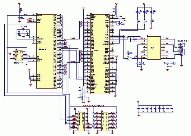
The CS8900A’s XTAL1(97) and XTAL2(98) pins are connected to a 20MHz crystal, which does not require an external capacitor due to its integrated capacitor at XTAL. The CS8900A has two different LED control pins: the LANLED (100) pin and the LINKLED (99) pin, which are used to control the LEDs to indicate the operating status of the CS8900A. The LANLED pin is connected to a red LED (D1), which is output low and lights the red LED when the CS8900A receives or sends data. LED (D2), which is lit when the CS8900A is connected to a working Ethernet network.
Circuitry related to the MSP430F149, in addition to the above and the CS8900A connection, there are JTAG (Joint Test Action Group) interface, crystal and reset circuit. Among them, the JTAG interface for programming and debugging, with a 14-pin connector to lead the four pins TCK, TDI, TDO/TDI for programming and debugging, can be directly connected to the MSP430 debugging tool FET (FLASH Emulation Tool). Users can also be level conversion chip MAX3221 MSP430F149 serial communication port also lead to achieve the desired function. MSP430F149 clock circuit part, you need to connect an 8MHz crystal and two 15pF capacitors.
The entire system is powered by a 3.3V power supply, green LED (D4) for the entire system power indicator. For system expansion needs, you can also MSP430F149 all unused I/O pins with connectors.
PCB (printed circuit board) design, filtered by bypass capacitors to provide a regulated power signal to the MSP430F149 and CS8900A. In order to get better system performance and reduce electromagnetic interference, it is best to be able to arrange the PCB as a four-layer board.
3.5 CS8900A interface to the local area network
The CS8900A has an on-chip 10M Ethernet transceiver with all the analog and digital circuitry for communication with the LAN, which can be directly connected to the LAN through an electromagnetic isolator E2023. Resistor R1 is used to connect the two receive lines, and resistors R2 and R3 are used to match the impedance of the two transmit lines. RJ45 is the network connector, which can be connected to a 10M or 100 network hub (hub).
- Software design
The software part of this design is divided into four main parts: Ethernet module, TCP/IP module, API (Application Programming Interface) and HTTP (Hypertext Transfer Protocol) service module, all programs are written in C language (to facilitate the expansion of the interface with other microcontroller systems) and compiled by IAR Workbench for MSP430 V2.10.
4.1 Ethernet module
The main purpose of the Ethernet part of the program is to drive the Ethernet controller CS8900A, provide interfaces to other modules in the form of functions to read and write CS8900A registers, and generate clocks to read and write CS8900A. The Ethernet program contains various configurations of the network interface, the most important of which is the configuration of the MAC (Media Access Control) address. 48 bits of the MAC address are stored in the program in six unsigned integer variables, each MAC address value must be unique and cannot be 0xFFFFFFFFFFFF.
The configuration process of the Ethernet controller is as follows: after the system is powered on, the function Init8900() is called to initialize the configuration of the Ethernet controller CS8900A, then the CS8900A is reset, the MSP430F149 sends the local MAC address to the CS8900A in the form of a configuration sequence word, and the CS8900A stores the MAC address in a register. . After configuration is complete, the MSP430F149 can read and write data to the CS8900A.
4.2 TCP/IP module
TCP/IP module is the key to the entire system software, defines the use of the network to send and receive data protocols, use the various read and write functions provided by the Ethernet module to receive or send data, and to the application layer to provide an easy-to-use API interface.
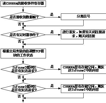
The most important function in the TCP/IP module is DoNetworkStuff(), whose main role is to perform TCP event processing and should be called periodically by the user program. In the function DoNetworkStuff(), some flag quantities are defined for marking the working state of the CS8900A and MSP430F149, and the workflow of this function is shown in Figure 3. Function DoNetworkStuff () is called the shorter the period, the better the performance of the system implementation of the TCP/IP protocol.
In order to better coordinate the received and sent data, the TCP/IP module allocates three buffers in SRAM, TxFrame1, TxFrame2, and RxTCPBuffer, where the main role of TxFrame1 is to provide buffer memory for TCP data frames (including Ethernet, IP, TCP frame headers) to be sent; the main role of TxFrame2 is to provide buffer memory for TCP non-data frames (including Ethernet, IP, TCP frame headers) and ARP, CIMP protocol frames; and RxTCPBuffer provides buffer memory for received TCP data. The main role is to provide buffer memory for TCP non-data frames (including Ethernet, IP, TCP frame headers) and ARP and CIMP protocol frames; RxTCPBuffer provides buffer memory for the received TCP data. The larger the buffer allocated, the faster the sending and receiving speed, as this reduces the lag caused by insufficient buffers.
Network communication connections can be established by calling the TCPPassiveOpen() or TCPActiveOpen() functions either actively or passively. The function TCPPassiveOpen() is mainly used to send packets into the buffer when a packet is detected, and the function TCPActiveOpen() is mainly used to send the packet to be sent into the buffer. Before actively sending a packet, the MAC address of the packet to be received is set and the local address is included in the packet. Once the connection is established, you can start sending data, and you can read the status of the connection through the corresponding interface function. When the data is sent, the connection can be closed by the function TCPClose().
In the process of sending and receiving packets, different tasks require different processing time, this time can be provided using the MSP430F149 timer Timer_A, but it must be noted that the timer Timer_A must be initialized before use, which is similar to the use of other microcontrollers. In order to reduce errors caused by unsuccessful packet transmission, when the receiver receives data, it should return a correct reception signal. When the transmitter exceeds the set time and still does not receive the correct reception signal, the TCP/IP module automatically retransmits the packet, and this process can be implemented through the corresponding variables and functions.
Although, the software procedures for handling TCP/IP protocols vary from company to company, fortunately, the compatibility of each company on TCP/IP protocols is very good, so there should not be much problem in communication between different programs as long as users program according to TCP/IP protocols.
4.3 API (Application Programming Interface)
In order to enable users to use the current application, but also to build their own requirements for embedded applications, in the entire software development process, should be left API functions, so that users do not need to have too much knowledge of the TCP/IP protocol can be based on the original program for secondary development. The software fully considers this point and leaves many AIP functions for users, mainly TCPClose(), TCPReleaseRxBuffer() and TCPTransmitTxBuffer(). The main purpose of TCPClose() is to close the open connection, before closing the connection, the sent packets are still in the send buffer to ensure correct delivery, and after closing the connection, the user has to reset the IP underground, reallocate the I/O port and re-establish the connection if he wants to re-establish the connection. The main purpose of this function is to be called after reading the data out of the buffer without saving the correctly read packets, so that the buffer can be freed up for new packets. The user can use the function TCPTransmitTxBuffer() to send data over an established connection, however, before using this function, the user has to check the SOCK_TX_BUF_RELEASED flag to determine if there is a transmit buffer available. In this design, variables (flags) for checking the connection status and sending and receiving status are also provided, such as SOK_ACTIVE, SOCK_CONNEDTED, etc.
4.4 HTTP Application
After doing the above, the user can set up an HTTP server to enable communication between different microcontrollers or workstations via TCP/IP protocol. HTML (Hypertext Link Markup Language) web page data can be saved in the MSP430F149’s on-chip FLASH memory. Web pages can be completed to receive data, send web data, close the connection and wait for other applications to connect. And, the user-created Web page, the ability to dynamically update data in real time. Of course, whether running HTML web applications on a regular computer or microcontroller, to achieve communication with other computers, it is necessary to set a single, valid MAC address, as previously described.
- Conclusion
With the development of network technology, the need for network connectivity and communication of micro embedded Internet terminals more and more, which can be applied not only in daily life, but also in many industrial sites, especially in those scattered, shared data or the need to share certain information in the industrial site embedded network terminal technology quality is more obvious. In addition, the MSP430 series microcontroller has very low power consumption, which is a good solution to the power supply problem in some special occasions. Thus, the design scheme discussed in this paper has great application prospects.