How to Build a High-Level Automated Driving Data Collection Platform
Preface
At present, autonomous driving technology is in a period of rapid development, with L3 gradually entering the mass production stage and L4/L5 autonomous driving level still in the development and verification stage, requiring a large amount of road test data for algorithm training and verification. In order to meet the needs of L4 and above algorithm training and verification, Northway provides road test data collection equipment and builds a data collection platform to provide customers with one-stop solutions. Typical customers, such as FAW Nanjing, have already applied it in the development of advanced autonomous driving technologies.
The data acquisition platform can provide a constant source of data for the development of perception algorithms such as artificial intelligence vision cameras, LiDAR, and high-precision positioning, and is a necessary tool for the development and validation of autonomous driving algorithms.

Sensor and acquisition equipment selection
The sensors required for high level autonomous driving are mainly 8MP front view binocular camera, 2MP surround view camera, 2MP/8MP peripheral view camera, solid state LIDAR, mechanical LIDAR, GPS/IMU/RTK, millimeter wave radar, etc. Typical sensor configurations and mounting locations are as follows.
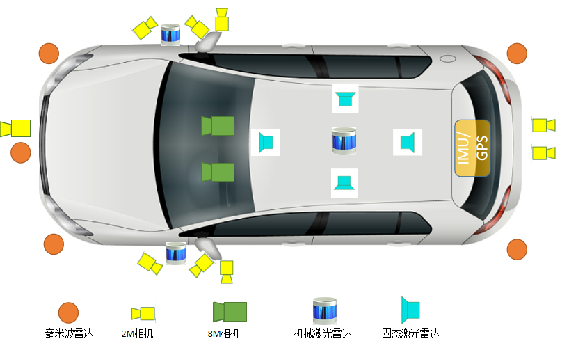
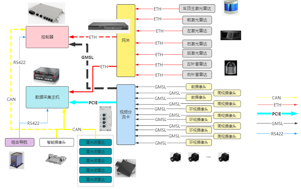
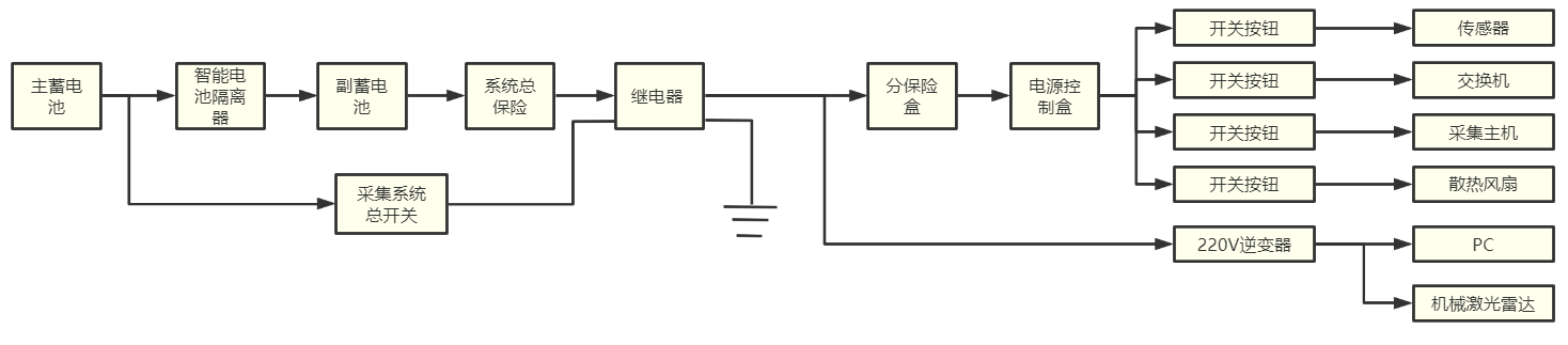
For the above sensor models to choose the corresponding models of acquisition equipment and acquisition host; need to focus on the data storage bandwidth and camera deserializer and transmission protocol and acquisition host processor performance. In addition, the data acquisition system needs to provide data shunting channels while collecting data to shunt the sensor data to the controller, so as not to affect the communication between the sensor and the controller while collecting data. The data routing of the acquisition system is shown in the figure below. Multiple LiDAR data are transmitted to the data acquisition host via Ethernet through the gateway, camera data are transmitted to the video shunt card through GMSL, and the shunt card transmits the data to the host while forwarding it to the ECU, and the host transcodes and stores the data. The target data of millimeter wave radar and intelligent camera are transmitted to the data acquisition host through CAN/ETH bus, and the combined inertial guidance data are transmitted to the data acquisition host through RS422/CAN/ETH; the host runs the acquisition software to collect and store all sensor data synchronously and provide the necessary display functions.
1.Sensor installation position and field of view calibration
After the sensor and acquisition equipment selection is completed, the sensor installation position and field of view are verified according to the acquisition platform digital model and sensor digital model, so that the sensor can perform better. Realize the collection of visual image information and LiDAR point cloud information within 360° of the acquisition platform, and reduce the blind area of the acquisition system.
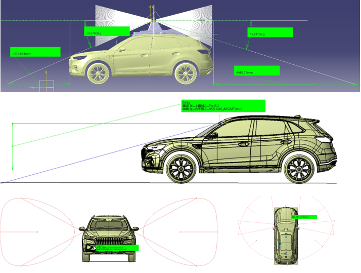
Figure. Sensor mounting position and field-of-view calibration
Bracket design
In order to ensure the sensor mounting position and angle, it is necessary to design the sensor bracket; mainly including LIDAR bracket, camera bracket, antenna bracket, trunk equipment bracket, etc. At the same time, in order to ensure the position and angle of the bracket installation, it is also necessary to design the positioning tooling for bracket installation.
Front view camera bracket
Peripheral view camera bracket
Surround view camera bracket
Solid-state LIDAR bracket
Blind-fill radar bracket
Trunk Equipment Bracket
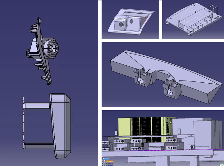
Figure. Sensor and equipment bracket
Equipment installation and commissioning
Once the bracket is designed and fabricated, the electrical modifications to the acquisition platform can begin; power needs to be supplied to each sensor, acquisition host and signal interface device and the output information from the sensors is obtained. It is necessary to calculate the total power of the whole system and select the appropriate power harnesses, fuse boxes, relays and system switches as well as power management devices.
Acquisition system power supply modification
The power supply system requires the addition of intelligent dual battery isolators and secondary batteries to ensure the stability of the power supply system; additional accessories such as relays, fuse boxes, switches and buttons are also required.
Video signal wire, LIDAR signal wire, millimeter wave radar signal wire, inertial wire harness, CAN signal wire harness arrangement
Sensor and bracket installation
Acquisition host and display terminal installation
Power on debugging
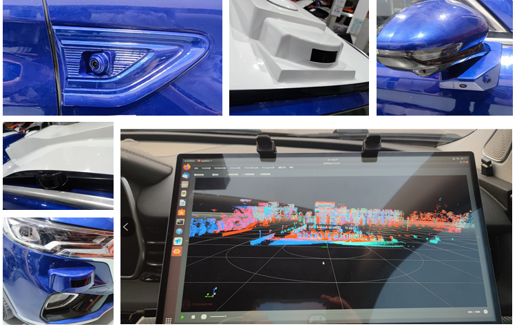
Figure . Sensor installation and commissioning
Sensor Calibration
Sensor calibration is a very important part of autonomous driving data acquisition and the basis of multi-sensor fusion. Automated driving first needs to determine the coordinate relationship between each sensor and the conversion relationship between each sensor and the coordinate system of the whole vehicle through calibration.
Sensor calibration is mainly divided into single sensor calibration and inter-sensor calibration. Single sensor calibration mainly includes camera calibration, LIDAR calibration and inertial guidance calibration; inter-sensor calibration mainly includes camera to camera calibration, camera to LIDAR calibration, LIDAR to LIDAR calibration.
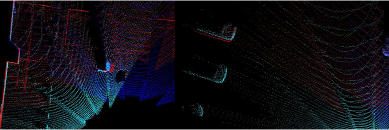
Figure . Lidar calibration
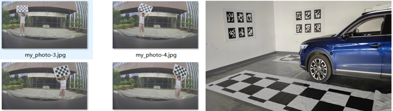
Figure . Camera calibration
Time synchronization
Since each sensor has its own time stamp, in order to ensure the time synchronization of each sensor, it is necessary to time the sensor and the acquisition system. The whole system obtains the GPS time from the combined inertial guide and times the time synchronization server; then the time synchronization server times the LIDAR and the acquisition host through the PTP gateway, so that the whole system uses the same time source (GPS time); at the same time, the time synchronization server outputs the trigger signal to trigger the camera and control the exposure moment of the camera, so as to realize the data synchronization of all sensors. data synchronization of all sensors.
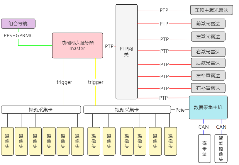
Figure . Time synchronization
Summary
Northlink not only provides complete road test data acquisition hardware and software, but also provides specialized engineering services according to user requirements, including hardware customization configuration and installation, and road test acquisition software engineering debugging and development, providing users with one-stop solutions to facilitate the subsequent verification of autonomous driving algorithms.