Gitzo CAN to PROFINET protocol gateway to servo slaves configuration case
This CAN to PROFINET protocol gateway JM-PN-CAN is connected to the PROFINET bus as a slave and connected to the CAN bus for reading and writing according to the node number.
The customer requires the Delta servo to connect to the Profinet network through the CAN to PROFINET protocol gateway to read and write to the Delta servo controller. 1200PLC is configured as follows.

Applications in automotive manufacturing, large instrumentation, industrial control, intelligent home and living community management, and robotics network interconnection.
At the same time, due to the characteristics of CAN bus itself, its application scope is no longer limited to the automotive industry, but to automatic control, aerospace, navigation, process industry, machinery industry, textile machinery, agricultural machinery, robotics, CNC machine tools, medical equipment and sensors, etc. CAN has formed an international standard and has been recognized as one of the most promising fieldbuses.
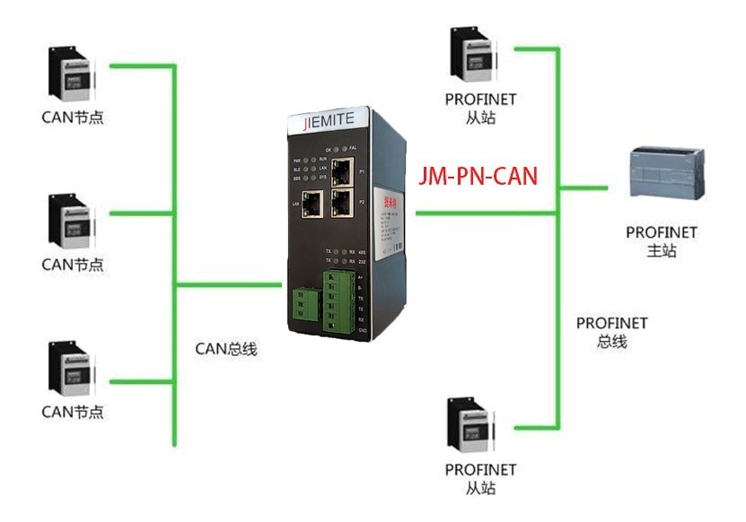
CAN to PROFINET Protocol Gateway JM-PN-CAN Configuration and Operation
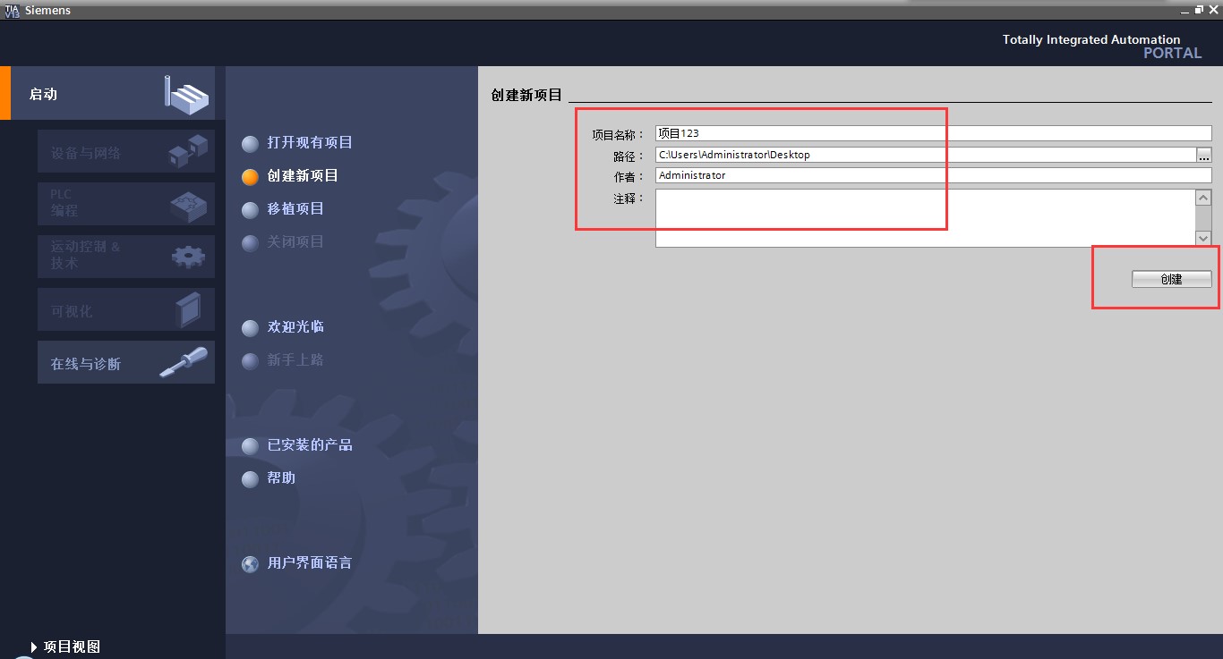
1 Create a new project
Open Protherm software and create a new project -> enter the project name -> Create. As shown in the figure.
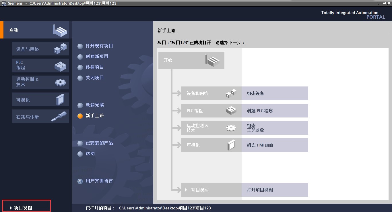
Click on the project view to enter the main screen, as shown in the figure.
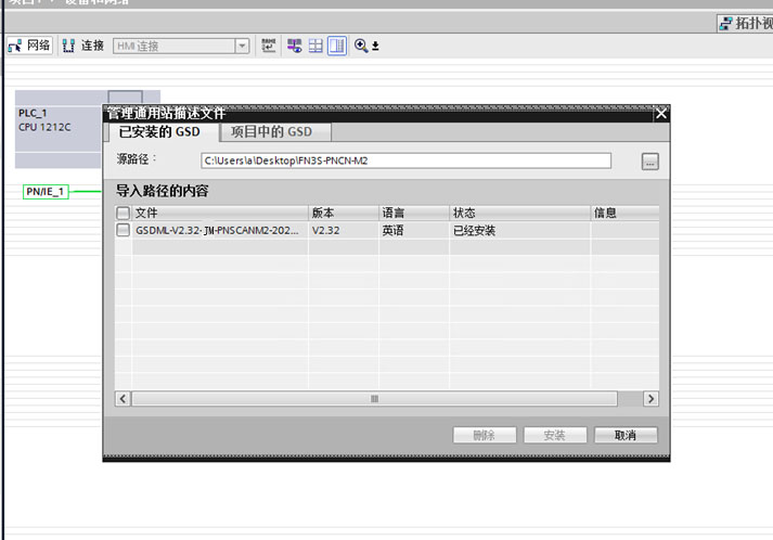
2 Install the GSD file of the CAN to PROFINET Protocol Gateway JM-PN-CAN
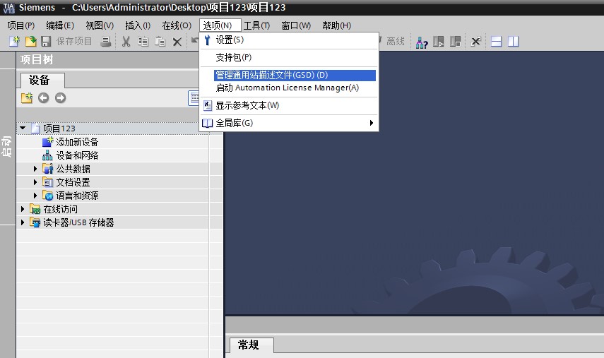
Select the menu bar “Options” – “Manage Generic Station Description File”, as shown in the figure.
Select the GSD file to be installed, click “Install”, and wait for the installation to finish, as shown in the figure.
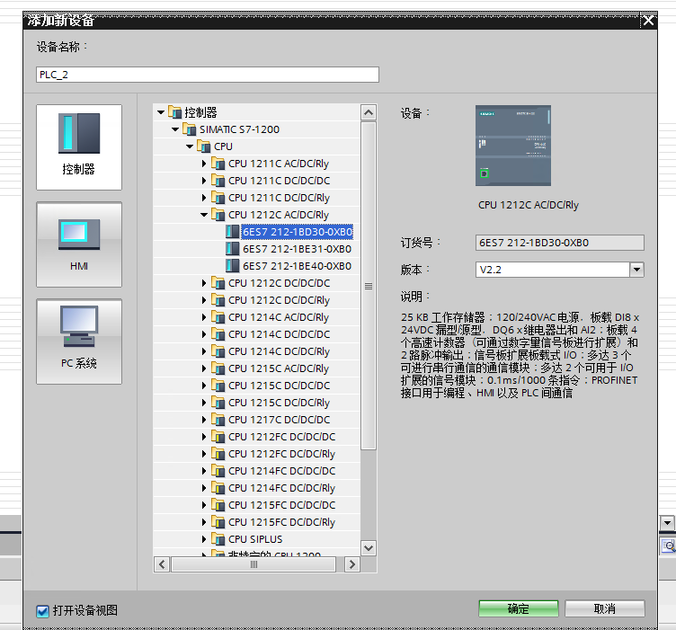
3 Add PLC and CAN to PROFINET Protocol Gateway JM-PN-CAN
Click on “Add New Device” in the “Project Tree” and select the corresponding PLC model in the controller.
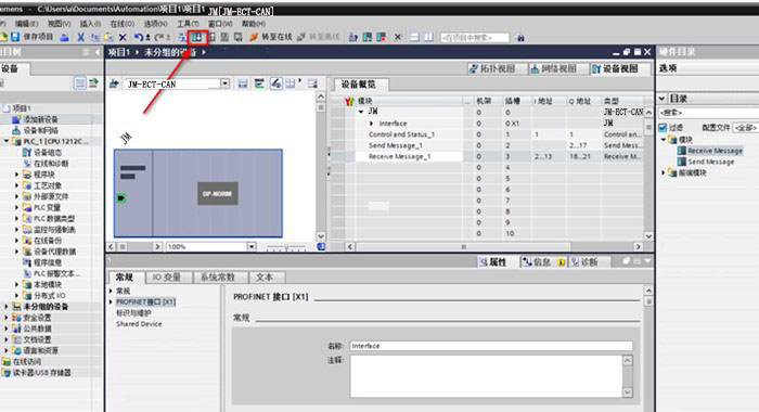
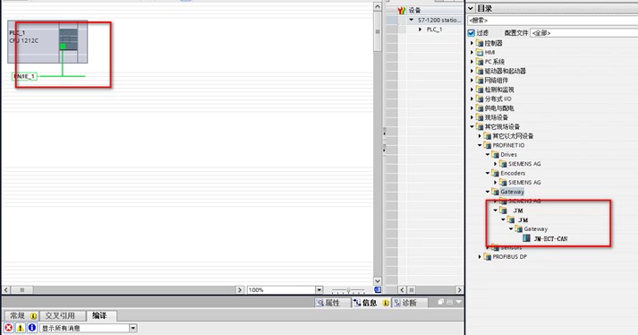
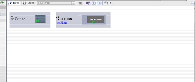
Double click on “Devices and Networks” in the “Project Tree”, and under the “Network View” window, select CAN to PROFINET Protocol Gateway JM-PN-CAN in the “Hardware Catalog” on the right side, as shown in the figure.
4 Set the device IP and device name of the project
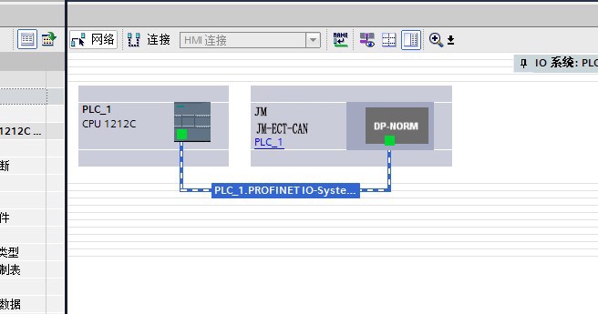
Click on the “Unassigned” icon of the CAN to PROFINET protocol gateway JM-PN-CAN and select “PLC_1.PROFINET interface” to establish the PROFINET connection between the PLC and the CAN to PROFINET protocol gateway The Profinet connection of JM-PN-CAN is shown in the figure below.
After the Profinet connection is established, as shown in the figure.
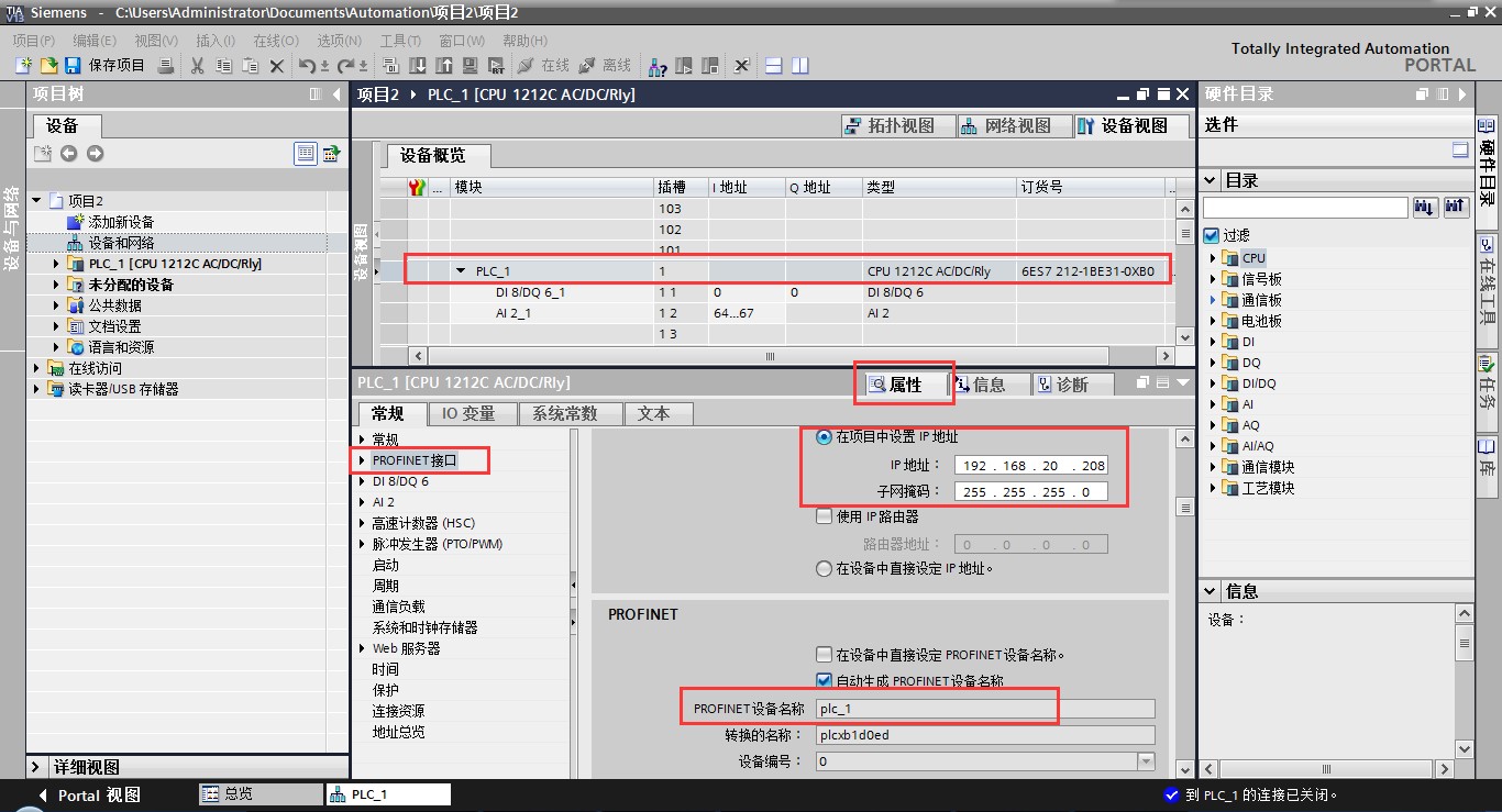
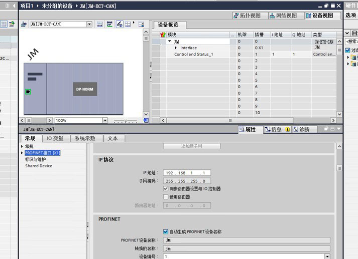
Double-click the PLC icon to enter “Device View”, click “PLC_1” in the device overview, and then set the IP address, subnet mask, device name, etc. of the PLC in the “Properties” window, as shown in Figure.
Double-click the CAN to PROFINET Protocol Gateway JM-PN-CAN icon, enter “Device View”, click “Interface” in the Device Overview, and then set the IP address and device name of the CAN to PROFINET Protocol Gateway JM-PN-CAN in the “Properties” window, as shown in Figure.

5 Modify the actual device IP and device name
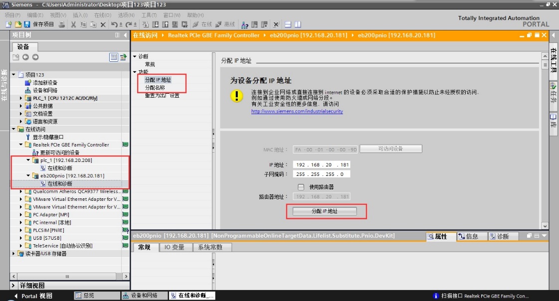
Connect the computer, PLC and CAN to PROFINET protocol gateway JM-PN-CAN with a network cable, select the computer’s network card in the “Project Tree”, and double-click “Update Accessible Devices”, as shown in the figure.
6 Set the CAN communication baud rate
Click on “Control and Status” in the “Device Overview”, then in the “Properties” window you can modify the CAN baud rate from 5Kbps to 1Mbps is optional. As shown in the figure.
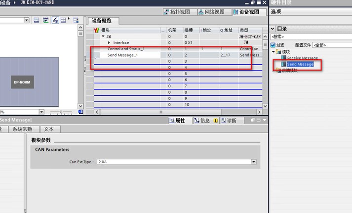
7 Add CAN Send Message
Select Send Message in the “Directory” list and add it to the module slot, as shown in the figure.
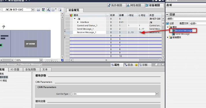
8 Add CAN Receive Message
Select Receive Message in the “Directory” list and add it to the module slot, as shown in the figure.
9 Compile and Download
At this point, we have completed the hardware and software configuration in Protherm software, and we will download the project to the Siemens S7-1200 PLC.
Under the “Devices and Networks” view, you can see the “Compile” button and the “Download” button, as shown in the figure.