Equivalent circuit model for dual transmission lines
01 Introduction of Equivalent Model
Kirchhoff’s voltage and current laws cannot be applied to longer wires. However, this problem can be solved in a clever way by dividing the transmission line into shorter segments (infinitesimal in the limit). These segments contain all the characteristics of the transmission line, such as loss, inductance, and capacitance characteristics. The advantage of dividing the wire into infinitesimal segments is the introduction of the concept of distribution parameters, which allows Kirchhoff’s law analysis on a microscopic scale.
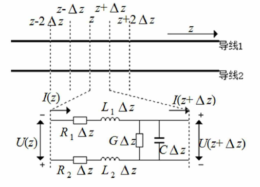
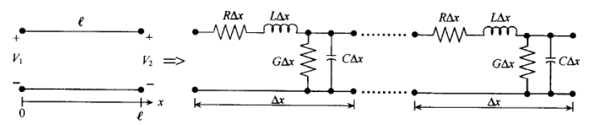
02 Equivalent circuit model for dual transmission lines
Assuming that attention is focused on a small segment located between z and z+∆z, note that each conductor segment is described in terms of a series connection of resistance and inductance. The capacitive effect due to the separation of charges caused by conductor 1 and conductor 2. Considering that all dielectrics have losses, the conductance G must also be introduced (refer to the schematic below).
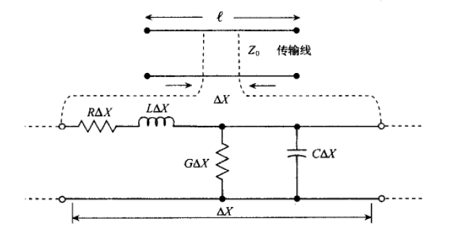
03 Equivalent circuit model of coaxial line
The coaxial line can be considered as a two-conductor system using a centralized parametric representation. Its equivalent circuit can be equated using the following model.
04 Advantages and disadvantages of equivalent circuits
The advantages can be expressed as follows.
Can represent an intuitive physical phenomenon.
can be used in a standard two-port model
Can be analyzed using Kirchhoff’s voltage and current laws.
can provide a microscopic to macroscopic basis of excess.
The disadvantages can be expressed as follows.
is in fact a one-dimensional analytical method that does not take into account the edge effects of the field on a flat plate perpendicular to the propagation direction, so that mutual interference with other circuit elements cannot be predicted.
material-related nonlinearities due to hysteresis effects are neglected.
is not suitable for direct time domain analysis.
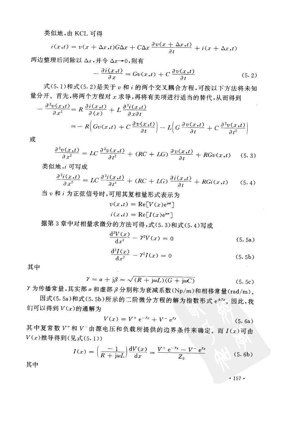
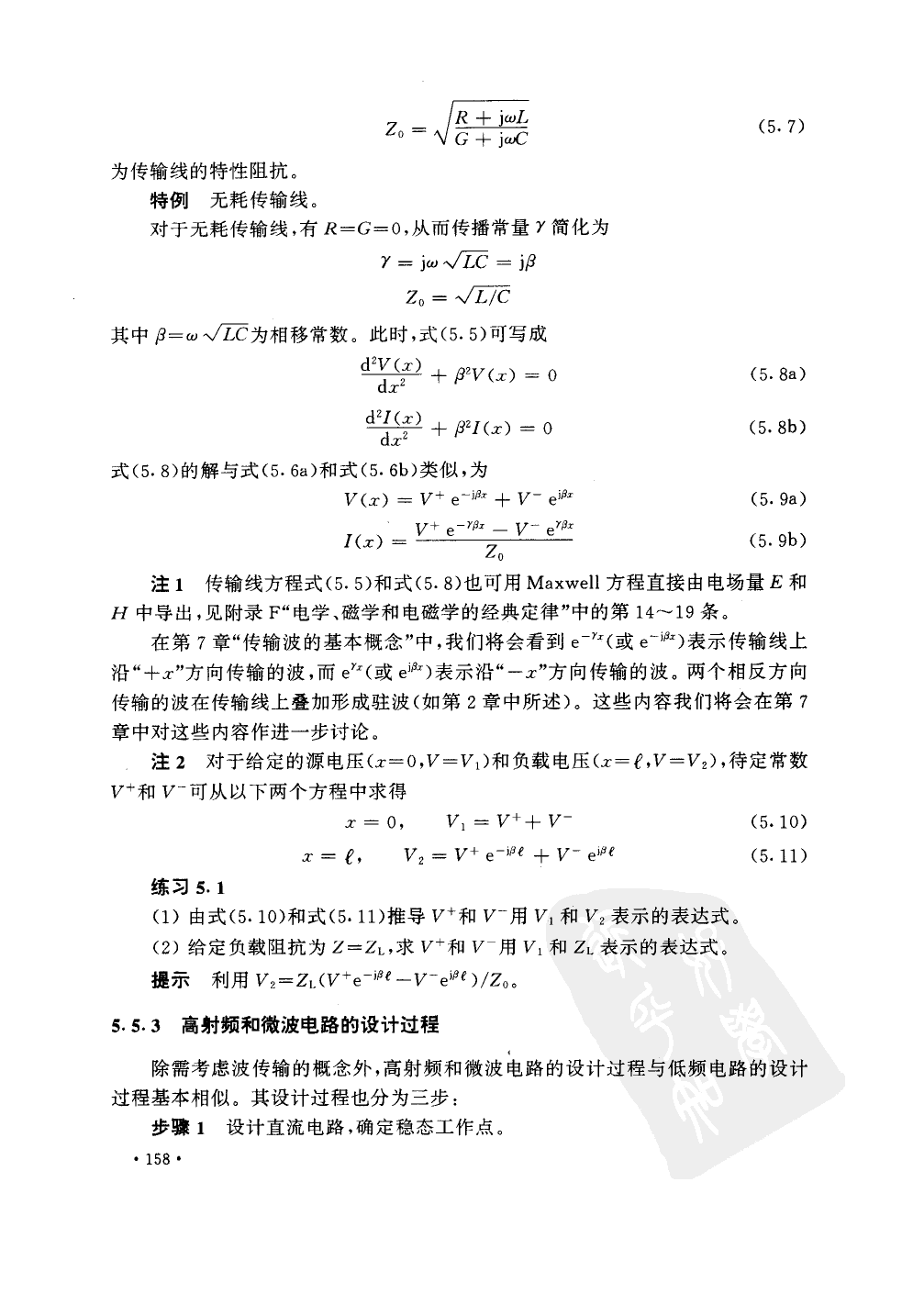
05 Voltage and current relationship of high frequency transmission lines
At high frequencies, the equivalent circuit model of the transmission line is as follows.
The following content quotes the promotion process inside “RF and Microwave Electronics”, you can take a look.