A crystal oscillator is an electronic circuit that uses the mechanical resonance of a vibrating crystal of piezoelectric material to create an electrical signal with a precise frequency. This frequency stabilized signal is often used to keep track of time and provide a stable clock source for digital integrated circuits, radios, computers, and other electronic devices.
Crystal oscillators provide higher frequency stability than other oscillator circuits like LC oscillators or RC oscillators, making them ideal references for radio transmitters/receivers and computer processors. This article provides an in-depth explanation of how crystal oscillators work and their applications.
What is a Crystal?
A crystal is a thin slice of piezoelectric material, usually quartz. Piezoelectricity means that deforming or compressing the crystal produces a voltage across it, while applying voltage causes mechanical deformation.
Quartz crystals exhibit very low losses and precise resonant frequencies, allowing them to vibrate millions of times per second in a very steady oscillation when excited. This ability to resonate so consistently makes them ideal for controlling oscillator frequencies.
Crystal Resonator Structure
The resonator structure of a crystal consists of a thin quartz wafer with metal electrodes deposited on opposite faces. The wafer is precisely cut to target vibrational modes based on crystallographic orientation. Common cuts include:
- AT Cut – Most common, with low temperature effects. Frequency range of 1-300 MHz.
- BT Cut – Wider temperature range than AT. Frequency range 1-200 MHz.
- SC Cut – Higher frequency operation up to 800 MHz with good temperature stability.
The size, thickness, shape, and orientation of the resonating quartz structure determines the resonant frequency. The electrodes allow applying an electric field to excite the mechanical vibration.
Quartz Crystal Properties
Quartz crystals have unique properties that make them exceptionally good at controlling oscillation frequencies:
- Piezoelectricity – Converts electrical and mechanical energy in both directions.
- High Q factor – Very low internal losses allow high Q resonance.
- Stability – Frequency varies little over temperature range.
- Precision cutting – Frequencies controlled to 5 parts per million.
- Convenient frequencies – Cutting provides common frequencies like 32.768 kHz.
- Robustness – Withstands mechanical shock and vibration.
Quartz provides by far the best all-around performance as a resonator for electronics. No other material compares.
Modeling the Crystal Resonator
The crystal resonator can be modeled in analogy to a simple harmonic oscillator:
- Mass – The quartz wafer’s physical mass.
- Spring Constant – Equivalent stiffness of quartz structure.
- Damping – Internal friction losses.
- Excitation – Applied AC voltage causing deformation.
- Resonance – Oscillation at mechanical resonant frequency.
This model helps understand the electrical behavior in terms of equivalent circuit elements.
Equivalent Circuit Model
The crystal resonator can be modeled by an equivalent electrical circuit:
- C0 – Total static capacitance between electrodes
- L1 – Mass equivalence as inductance
- C1 – Spring constant equivalence as capacitance
- R1 – Resistance modeling mechanical losses
The resonant circuit analogy enables analyzing crystal circuits through normal circuit techniques.
Series and Parallel Resonance
The crystal equivalent circuit exhibits both series and parallel resonance:
Series Resonance
At series resonance, the capacitive and inductive reactances cancel, leaving just the motional resistance R1. Frequency where impedance is minimal.
Parallel Resonance
At parallel resonance, the capacitive and inductive reactances are equal, creating high impedance. Frequency where impedance is maximal.
Crystal oscillators are designed to operate at series resonance. Parallel resonance is a “spurious” response to be avoided.
Drive Level and Activity Dip
The amplitude of the AC excitation voltage affects the crystal’s oscillating characteristics:
- Low Drive – Underdrive distorts the amplitude vs. frequency response.
- High Drive – Overdrive causes additional vibration modes and frequency shifts.
- Optimal Drive – When driven at manufacturer specified voltage, a pronounced dip in frequency appears at the nominal resonant frequency. This activity dip determines the actual oscillation frequency.
Operating at the proper drive level ensures the circuit oscillates at the intended frequency.
Crystal Packaging
Crystal resonators are fabricated in several package types:
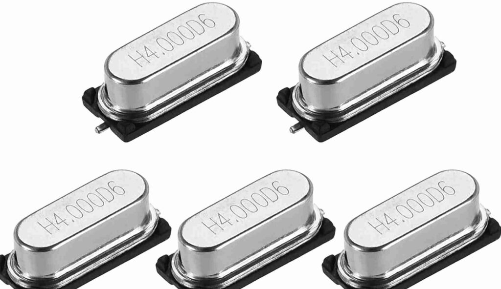
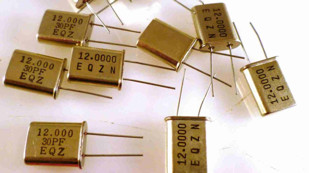
Through Hole Packages
- HC-49 – Metal can with radial wire leads soldered on PCB. Common for quartz crystals.
- HC-49/U – Improved shock resistance. Popular for microcontrollers.
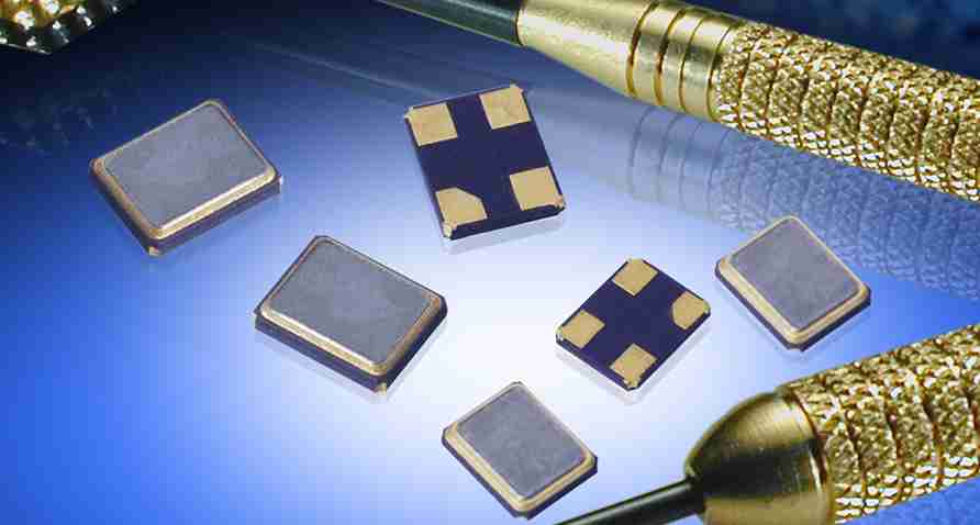
Surface Mount Packages
- SMD – Miniature SMD package. Low cost.
- Absence of leads reduces stray capacitances.
Common for consumer electronics.
Choosing the right package depends on PCB mounting requirements, cost, and application environment. Crystals are very robust devices.
Using a Crystal in an Oscillator
The high Q resonance of the crystal forms the frequency determining element in an oscillator circuit. Common oscillator circuit configurations include:
Pierce Oscillator
Simple circuit using a single inverter amplifier with capacitive feedback via the crystal. Very common.
Colpitts Oscillator
LC oscillator modified to have a crystal replacing the LC resonant circuit. Provides good stability.
Negative Resistance Oscillator
Uses a negative resistance device like a tunnel diode to cancel losses in crystal. Handles multiple megahertz frequencies.
CMOS Oscillator
IC oscillator circuit biased to operate at crystal parallel resonance. Simple and inexpensive.
The choice of circuit depends on frequency, cost, complexity, and other requirements. But all rely on the crystal’s mechanical resonance to stabilize the oscillations.
Frequency Accuracy and Tolerance
A major advantage of crystal oscillators is their high frequency accuracy and precision. Frequency tolerance relative to nominal value is specified by these precision classes:
| Precision Class | Frequency Tolerance | Example Frequencies |
|---|---|---|
| Industrial | ±0.1% to ±0.0005% | 1 MHz ± 1 kHz |
| Miltary | ±0.005% to ±0.0001% | 10 MHz ± 50 Hz |
| Space | ±0.001% to ±0.00001% | 50 MHz ± 5 Hz |
Tighter tolerances increase cost but provide extremely precise and accurate frequency standards.
Frequency Stability and Atomic Clocks
Beyond just accuracy to a nominal value, the frequency stability of a crystal oscillator refers to how precisely it maintains the same oscillation frequency over time, temperature changes, and environmental conditions. Stability is critical for radio, clocking, and measurement applications.
Atomic clocks which use the precise energy transitions of atoms like cesium or rubidium as a reference provide the most stable frequency standards known, 100x better than even premium crystal oscillators. GPS systems rely on rubidium and cesium atomic clocks.
But smaller crystal oscillators provide practical and affordable high-quality frequency references for widespread everyday electronic devices.
Features and Parameters
Some key parameters and features to consider when selecting a crystal oscillator:
- Frequency – Fundamental resonant frequency, typically between 1 kHz and 200 MHz.
- Frequency tolerance – Precision and accuracy class.
- Stability – Frequency drift over time and temperature.
- Drive level – Optimal input voltage for specified performance.
- Load capacitance – Recommended external capacitive load for oscillation.
- Aging – Change in frequency over operating lifetime.
- Operating temperature range
- Output waveform and amplitude – Sine wave, clipped sine, square wave.
Crystal Oscillator Examples
Some examples of typical crystal oscillator circuits:
Microcontroller Oscillators
Provide clocking reference signal for digital logic chips like microcontrollers and microprocessors. Common frequencies are 1 MHz to 60 MHz.
Clock Generators
Generate standard clock frequencies like 10 MHz or 32.768 kHz with excellent accuracy and stability for devices that need precise timing.
Radio Frequency Control
Accurately generate a specific radio transmission frequency like 433 MHz for low power wireless transmitters and receivers.
Real-time Clocks
Keep extremely accurate time over many years using a 32.768 kHz crystal. Used in computers, clocks, instruments.
Sensor References
Provide timing signals for measurement and sampling control of sensors. Allows precise timekeeping between samples.
Choosing the Right Crystal
Here are some guidelines for selecting the optimal crystal for an application:
- Match the specified nominal frequency required.
- Ensure supply voltage and oscillator circuit can provide recommended drive level.
- Have load capacitance within crystal’s rating for reliable startup and oscillation.
- Choose frequency tolerance needed for accuracy purposes. Tighter tolerance increases cost.
- Consider the operating temperature range and crystal cut. Some cuts handle wider ranges better.
- Assess impact of aging and frequency stability on the application.
Matching the crystal parameters to the circuit and application constraints results in optimal oscillator performance.
Crystal vs. Ceramic Resonators
Ceramic resonators are also piezoelectric materials optimized for higher frequencies above 30MHz where quartz becomes difficult to work with.
Crystal Advantages
- Lower cost for < 20 MHz
- Better aging and temperature stability
- Available in > 100 MHz range (3rd overtone)
- Higher quality factors and precision
Ceramic Advantages
- Smaller size
- Integration into one package with oscillator
- Very fast start-up time
Either device provides good frequency references. Choice depends on the specific requirements.
Ovenized Crystal Oscillators (OCXO)
Ovenized oscillators encapsulate the crystal inside a temperature controlled high stability oven, keeping the crystal at a precise constant temperature. This minimizes frequency drift, providing extremely high long-term stability on the order of parts per billion.
The oven insulation, heater, and temperature regulation allows year-to-year frequency consistency unattainable with non-ovenized oscillators. This makes OCXOs ideal for lab and calibration instruments.
Temperature Compensated Crystal Oscillators (TCXO)
TCXOs utilize analog or digital temperature compensation circuitry to actively monitor and adjust the oscillator frequency over changing temperatures.
A temperature sensor feeds back into a compensation network that maintains the output frequency with 2-3x better stability than uncompensated units. This allows good stability over wide operating temperature ranges.
TCXOs provide accuracy nearly as good as ovenized oscillators without the high power consumption and slow warm-up time. This makes them well suited for mobile and battery operated equipment.
Microcomputer Compensated Crystal Oscillators (MCXO)
MCXOs take temperature compensation a step further by continuously optimizing the trimming control of the oscillator in real-time using a microprocessor and DAC network. This can provide performance approaching OCXOs at lower cost.
Digitally controlled compensation allows dynamically adapting to changing environmental conditions beyond just temperature, like vibration, orientation, aging, input voltage changes, etc. Smart algorithms running on the integrated microcontroller provide robust frequency stability.
Voltage Controlled Crystal Oscillators (VCXO)
VCXOs allow electrically adjusting the oscillator’s frequency slightly by means of a control voltage. Changes are generally on the order of 0.5% to 1% above and below the center frequency.
Control voltage shifts the resonant peak higher or lower in frequency. This allows things like fine tuning radios or synthesizer pitches with greater precision than stepping through fixed crystal frequencies.
Phase Locked Loop Stability
Many applications don’t directly need an ultra-stable reference oscillator. Rather, they need one fixed stable frequency that is derived from a reference.
Phase locked loop (PLL) integrated circuits can take in the frequency from a good crystal oscillator, then amplify it to a very high multiple while preserving the original stability and precision. A 100 MHz carrier might be generated by a 10 MHz oscillator.
This allows lower frequency crystals to be used as a stable low cost high precision frequency basis for radios, clock multipliers, microprocessors, and other electronics.
Frequently Asked Questions
- How does a crystal produce an electrical oscillation?
The piezoelectric effect causes the crystal to mechanically vibrate when driven by AC voltages applied to its electrodes. This vibration in turn generates an oscillating voltage across the crystal at its resonant frequency that can be amplified to sustain oscillations.
- Can any crystalline material be used in crystal oscillators?
No, quartz is almost universally used due to its superior piezoelectric properties and ability to be precisely cut to target frequencies. Some other piezoelectric crystals like Rochelle salt are used in specialty applications.
- What are overtone crystals?
Overtone crystals are cut to resonate on their 3rd, 5th, or higher odd harmonic rather than the fundamental mode. This allows higher frequencies like 60 MHz from a 20 MHz crystal. They are more complex to produce but cut component count.
- How are tuning fork crystals different from regular quartz crystals?
A tuning fork crystal has two tines that vibrate in antiphase rather than a single plate. The resonance mode is an unusual but useful type. Tuning fork crystals are more tolerant of vibration and shock.
- Why do older analog wristwatches use 32.768 kHz crystals?
The extremely low frequency allows using a tiny quartz crystal resonator while still providing excellent timekeeping accuracy. Low power oscillator circuits can extract long battery life dividing the signal down to one tick per second.