The presence of the junction capacitance causes the base current ib to be bypassed. Thus, the base current ib′ that really flows through the emitter junction is reduced. And only the real base current flowing through the emitter junction is amplified. The higher the frequency, the lower the capacitance of the junction capacitor, the more significant the bypassing effect of the junction capacitor, the lower the current amplification β of the transistor and the lower the gain of the amplifier.

Today we will learn the constraints of high frequency gain when using op amps!
I. Junction capacitance and the effect of junction capacitance
In the previous few articles we know that the two inputs of the op-amp are actually the base of two transistors, then there will certainly be junction capacitance. This is also one of the factors that constrain the high frequency gain.
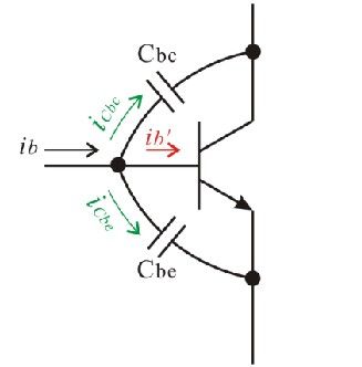
The presence of the junction capacitance allows the base current ib be bypassed. Thus, the base current ib′ that really flows through the emitter junction is reduced. And only the base current that really flows through the emitter junction is amplified. The higher the frequency, the lower the capacitance of the junction capacitor, the more significant the bypassing effect of the junction capacitor, the lower the current amplification β of the transistor and the lower the gain of the amplifier.
The emitter junction of a transistor in an amplifier must be in a forward biased state and the collector junction in a reverse biased state, so the junction capacitance of the emitter junction is much larger than that of the collector junction. On the surface, it appears that the junction capacitance of the emitter junction is the main factor in the drop in high frequency gain, but in reality, it is the junction capacitance of the collector junction that is the decisive factor in the drop in high frequency gain of the amplifier.
For a common-injection amplifier, the junction capacitance of the collector junction is connected across the collector and the base. Whereas the collector is often the output of the amplifier, the base is the input of the amplifier. The capacitance across the inverting input and output of the amplifier is subject to a special phenomenon – the Müller effect – and this is what makes the junction capacitance of the collector junction a decisive factor in the high frequency gain of the amplifier.
ii. the miller effect
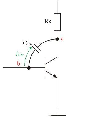
The op-amp input stage is a differential amplifier. The operating state of a differential amplifier under a differential signal is equivalent to that of a common-shot amplifier.
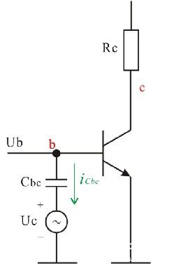
It should be noted in the diagram that the base voltage Ub is the input voltage and the collector voltage Uc is the output voltage.
Therefore, the gain of the amplifier is

Note also that the common-injection amplifier is an inverting amplifier, so there is a negative sign in the expression for the gain.
In the figure, the current iCbc flowing through the collector junction capacitor Cbc is
iii. miller capacitance
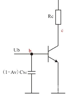
The circuit can be redrawn as follows.
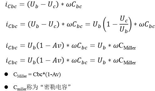
The capacitance across the output of the amplifier and the inverting input can be equated to the capacitance of the input to ground, which is (1-Av) times the capacity of the original capacitance – a phenomenon known as the “Müller effect”
Summary
- As you can see, the higher the voltage gain Av of the amplifier, the larger the equivalent Miller capacitance. –so the collector junction capacitance tends to be the main factor governing the high frequency gain of the amplifier.
- The equivalent Miller capacitance to the base will form an RC low-pass network with the output resistance of the preamp circuit, thus limiting the bandwidth of the amplifier.
- Due to the parasitic nature of the collector junction capacitance and due to the Miller effect, the product of the amplifier’s voltage gain and the amplifier bandwidth becomes a constant. –The higher the gain, the lower the bandwidth, and vice versa.
- Of course, if a capacitor is artificially connected between the collector and the base, the low-pass cut-off frequency of the common-injection amplifier will be artificially reduced, i.e. the bandwidth of the common-injection amplifier will be artificially reduced.
- Therefore, both the common-source amplifier and the differential amplifier can be equated as a cascade of an ideal, infinitely wide bandwidth amplifier and an RC low-pass network.