In practical applications of microcontrollers, functions such as precise time delay, timed scanning, counting the number of events and growing a certain frequency of sound are often used.
All these functions need to be implemented in the timing circuit for timing and counting.
The 80C51 series microcontroller has two internally integrated programmable 16-bit timer/counters, referred to as T0 and T1. Each timer can work independently and can be set to both timing and counting modes, with four operating modes available.

Structure of Timer/Counter
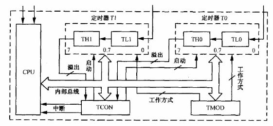
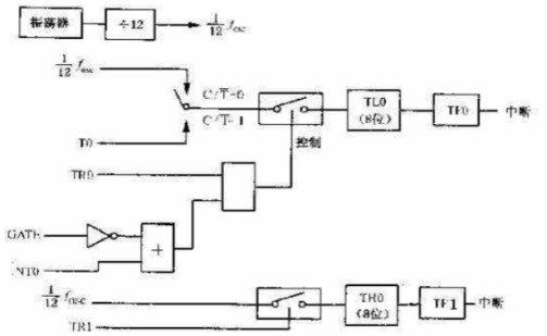
The core of the internal timer counter of the 80C51 microcontroller consists of two 16-bit plus 1 count registers T0 and T1, each count register is divided into high 8-bit THx and low 8-bit TLx accessed separately.
The clock source can be either internal or external. When the internal clock source is selected, the clock pulse sequence is generated internally by the microcontroller; when the external clock source is selected, the external clock pulse sequence is input from pins P3.4 and P3.5.
Timer/Counter Function
When used as a timer, the internal clock source is often selected, with the clock signal provided internally by the microcontroller at a fixed frequency.
When used as a counter, an external clock source is often used, the signal is input from the corresponding pin to count the number of external events occurring.
1) Counting function
The falling edge of the clock signal is valid, the microcontroller will sample the level state of the external input clock signal during S5P2 of each machine cycle, when the signal sampled twice in succession is 1 and 0, the microcontroller considers the external input a falling edge, at which time the counter count value during S3P1 of the next machine cycle plus 1.
Since it takes two machine cycles to sample one falling edge, i.e. 24 oscillation cycles, the maximum frequency of the external input counting pulse is 1/24 of the microcontroller oscillation frequency.
2) Timing function
The internal clock source is selected, and the frequency is 12 divisions of the microcontroller master clock. According to the length of the timing time and the main clock frequency of the microcontroller, the initial value of the timing/counter should be calculated, and then start the timer to start timing.
When the timing time is up, generate an interrupt or software query to wait for the time to end.
Timing and counting are the same in essence, both are achieved by counting the number of falling edges of the clock signal.
Timer/counter mode registers and control registers
1) Operation mode register TMOD
TMOD is used to set the timer/counter start mode, the selected clock source, and the operating mode. It is not addressable by bit and can only be programmed for the whole register.
The high 4 bits control Timer/Counter 1 and the low 4 bits control Timer/Counter 0.
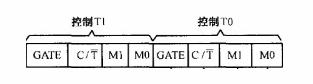
GATE: Counter gate control bit, used to determine whether the start is controlled by the input level of the external interrupt input pin.
When it is 0, the pin INTx level has no effect and the counter starts working as soon as the start control bit TRx is activated; when it is 1, the counter will start working only when INTx is 1 and TRx is also 1. This setting is often used to measure the pulse width of the high level of the INTx pin.
C/T: clock selection control bit.
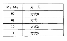
M1M0: operating mode selection bit.
2) Control register TCON
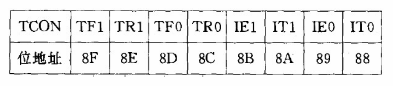
The high 4 bits are used to control the start, stop and interrupt request flags of the timer/counter; the low 4 bits are used to control the interrupt request flags and trigger mode of the external interrupt.
TF1: Timer/Counter1 interrupt request flag bit.
TR1: Timer/Counter1 start control bit.
TF0: Timer/Counter0 interrupt request flag bit.
TR0: Timer/Counter0 start control bit.
4 operation modes of Timer/Counter
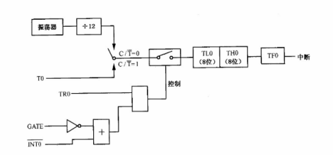
1) Mode 1: 16-bit timer/counter
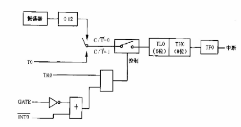
2) Mode 0:13-bit Timer/Counter
The 13-bit timer consists of the 8 bits of THx plus the low 5 bits of TLx to form a timer/counter. When the low 5 bits of TLx are counted full and overflowed, it feeds directly to THx.
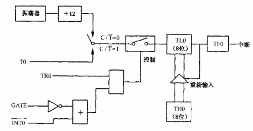
3) Mode 2: 8-bit Timer/Counter with Automatic Reload
The 16-bit counter is divided into two independent parts, where THx is used as the count initial value register due to storing and holding the initial value, which is set by software, and TLx is used as an 8-bit counter.
4) Mode 3
For T1, setting to mode 3 is equivalent to making TR1=0 to stop counting, which has no practical meaning. Therefore only timer/counter 0 can work in mode 3.