5.1 Interrupt concept
Interrupt means that when some unexpected situation occurs during the operation of a computer that requires the intervention of the host computer, the machine can automatically stop the running program and move to the program that deals with the new situation, and then return to the original suspended program to continue running after the process is completed.
Suppose a person is watching TV at home, then suddenly the doorbell rings, the person has to stop watching TV to open the door, then close the door and continue to come back to watch TV, the action of watching TV in this example is the regular computer operation process, the doorbell rings is equivalent to an interrupt signal (interrupt request), the user then stops watching TV (interrupt the current program) to open the door (interrupt response), after closing the door (interrupt processing ends) to continue watching TV (continue to execute the current program). After closing the door (end of interrupt processing) continue to watch TV (continue to execute the current program). This whole process is how the CPU handles the interrupt when it occurs.

Or the above example, now suppose the doorbell rings when the water is boiling, at this time the user can choose to open the door first and then turn off the water, you can also choose to turn off the water first and then open the door, this sequential relationship is the interrupt priority, assuming that the interrupt priority of the doorbell is higher than the priority of boiling water, it will open the door first and then turn off the water, and vice versa, it will turn off the water first and then open the door, this is for two or more interrupts occurring at the same time The CPU executes interrupts according to the interrupt priority.
When CPU is processing a certain event A, another event B occurs requesting CPU to deal with it quickly (interrupt occurs), then CPU temporarily interrupts the current work and turns to deal with event B (interrupt response and interrupt service), wait until CPU finishes processing event B, then go back to the place where the original event A was interrupted to continue processing event A (interrupt returns), this process is called interrupt.
Conventional 51 microcontroller has five interrupt sources, interrupt priority from high to low: external interrupt 0 (interrupt0), timer 0 (interrupt1), external interrupt 1 (interrupt2), timer 1 (interrupt3) and serial port interrupt (interrupt4).
The root cause of the CPU interrupt is called the interrupt source. The CPU temporarily interrupts the original transaction A to process event B. After processing event B, it returns to the original interrupted place (i.e., breakpoint), which is called interrupt return. The component that implements the above interrupt function is called the interrupt system (interrupt mechanism).
5.2 Introduction to 51 MCU Interrupts
The interrupt structure of the 51 microcontroller is shown in the following figure.
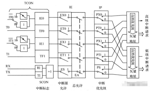
From the diagram, we can see that to configure external interrupts, we must first configure IT0 (or IT1, timer and serial port do not have this item), select the triggering method according to the assigned value, there are two types of external interrupt triggering methods, falling edge triggering and high level triggering, then configure the corresponding interrupt enable, EX0, ET0, EX1, ET1, ES, and finally turn on the total interrupt EA.
5.3 External Interrupt Related Registers
5.3.1 Interrupt control register IE
Register address: 0xA8
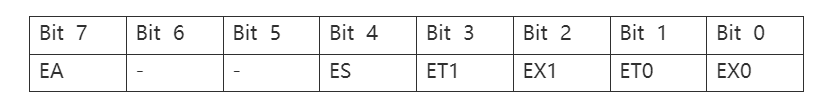
Bit 7: Total interrupt enable
0: Off
1: On
Bit 4: Serial interrupt enable
0:Off
1: On
Bit 3: Timer 1 interrupt enable
0: off
1: On
Bit 2: External interrupt 1 interrupt enable
0: off
1: On
Bit 1: Timer 0 interrupt enable
0: off
1: On
Bit 0: External interrupt 0 interrupt enable
0: off
1: On
5.3.2 Interrupt Flag Register TCON
Register address: 0x88

Bit 7: Timer/Counter1 overflow interrupt request flag bit
0: No interrupt is generated
1: Interrupt generated
Bit 6: Timer/Counter1 enable
0: Timer/Counter1 off
1: Timer/Counter1 enabled
Bit 5: Timer/Counter0 overflow interrupt request flag bit
0: No interrupt generated
1: Interrupt generated
Bit 4: Timer/Counter0 enable
0: Timer/Counter0 off
1: Timer/Counter0 enable
Bit 3: External interrupt 1 interrupt request flag bit
0: No interrupt generated
1: Generate interrupt
Bit 2: External interrupt 1 trigger mode control bit
0: Level trigger mode
1: Edge trigger mode (falling edge valid)
Bit 1: External interrupt 0 interrupt request flag bit
0: No interrupt generated
1: Generate interrupt
Bit 0: External interrupt 0 trigger mode control bit
0: Level trigger mode
1: Edge trigger mode (falling edge valid)
5.3.3 Interrupt priority control register IP
Register address: 0xB8
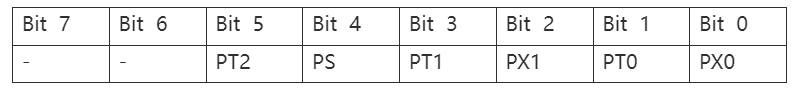
Bit 5: Timer/Counter2 priority setting
Bit 4: Serial port priority setting
Bit 3: Timer/Counter 1 priority setting
Bit 2: External interrupt 1 priority setting
Bit 1: Timer/Counter 0 priority setting
Bit 0: External interrupt 0 priority setting
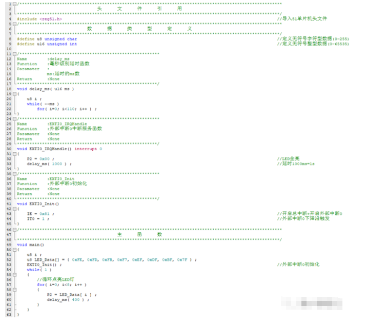
5.4 Routine Analysis
5.4.1 Principle diagram
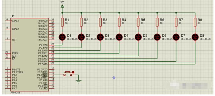
5.4.2 Implemented functions
When no interrupt occurs, D1~D8 are cyclically lit in order, only one LED is lit at a time, when the key is pressed, the LED is fully lit for 1s, and after 1s the LED continues to be cyclically lit from the position where it was disconnected (not allowed to be lit from the beginning).
5.4.3 Source Code