A microcontroller, also known as a monolithic microcontroller, is not a chip that completes a certain logical function, but a computer system integrated into a single chip. It is equivalent to a miniature computer, and compared to a computer, a microcontroller is only missing the I/O device. In a nutshell: a chip becomes a computer. It is small, light, inexpensive, and provides convenient conditions for learning, application and development. At the same time, learning to use microcontrollers is the best choice to understand the principles and structure of computers.

Microcontrollers have been used in a wide range of fields, such as smart meters, real-time industrial control, communication devices, navigation systems, home appliances, etc.
Microcontroller is the core component of embedded system, the circuit using microcontroller is much more complex, but when changing and adding new functions, the circuit with microcontroller is easier to implement, which is exactly the reason why electrical equipment uses microcontroller. So what are the difficulties that need attention in the design of the microcontroller circuit?
First, the choice of microcontroller pull-up resistors
We can see that the reset circuit resistance R1 = 10k RST is high, and when R1 = 50 RST is low, it is obvious that R1 = 10k is wrong, the microcontroller has been in the reset state can not work at all. The reason for this is that the RST pin contains a triode, even in the cutoff state there will be a small amount of cutoff current, when R is taken very large, the weak cutoff current through the high level.
Second, the LED series resistance calculation problem
Usually red SMD LED: voltage 1.6V-2.4V, current 2-20mA, in 2-5mA brightness has changed, 5mA above the brightness basically no change.

Third, the port appears to be insufficient
This can be achieved with the help of expansion chips, such as the three-eight decoder 74HC138 to expand.
Four, filter capacitor
Filter capacitor is divided into high frequency filter capacitor and low frequency filter capacitor.
1, high-frequency filter capacitor is generally used 104 capacitance (0.1uF), the purpose is to short-circuit the high-frequency component, to protect the device from high-frequency interference. Ordinary IC (integrated) devices between the power supply and ground are added to remove high-frequency interference (air static).
2, low-frequency filter capacitors are generally used electrolytic capacitors (100uF), the purpose is to remove low-frequency ripple, store part of the energy, stabilize the power supply. Mostly connected to the power supply interface, next to high-power components, such as: USB excuse, stepper motor, 1602 backlight display. Withstand voltage value of at least two times higher than the maximum system voltage.
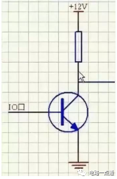
Five, the role of transistors
1, the role of the switch.

LEds6 is cutoff when high level and on when low level.
Calculation of current limiting resistance: collector current is I, then the base current is I/100 (amplification is involved here, the collector current is 100 times the base), PN junction voltage 0.7V, R = (5-0.7)/(I/100)
2, amplification: the collector current is 100 times the base current
3, level conversion
When the base is high, the triode is on, the right wire is grounded to low, when the base is low, the triode is cut off and the output is high.
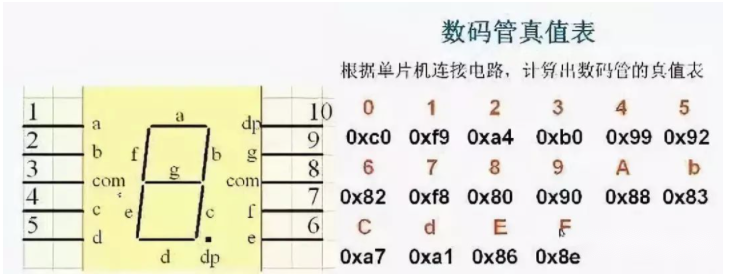
Six, the digital tube related issues
Seven, the current voltage drive problem
Due to the limited output of the microcontroller, when the load is a lot of time need to add another driver chip, such as 74HC245.
Eight, pull-up resistors
Pull-up resistor selection principles
1, from saving power consumption and the chip’s ability to fill the current should be large enough to consider; large resistance, small current.
2, from the drive current to ensure sufficient consideration should be small enough; small resistance, large current.
3, for high-speed circuits, too large pull-up resistor may lead to edge flattening.
Comprehensive consideration: pull-up resistor commonly used value between 1K to 10K selected, the same pull-down.
Pull-up and pull-down resistors, pull-up is the uncertainty of the signal through a resistor embedded in the high level, pull-down the same.
1, level conversion, increase the output level parameter value.
2, OC gate must be added to the pull resistor to use.
3, increase the ordinary IO pin drive capability.
4, overhanging pins pull up and down to resist interference.
Nine, crystal oscillator and reset circuit
Crystal circuit
1, crystal oscillator selection.
According to the actual system needs to choose, 6M, 12M, 11.0592M, 20M, etc..
2, load capacitance.
Ground to connect two 10 to 30pF capacitor can be, commonly used 20pF.
3, multimeter measurement crystal.
Directly with the red pen to the crystal pins, the black pen to GND, measure the voltage can be. Reset circuit
The internal circuitry of the microcontroller is set to a definite state, all registers are initialized.
The reset time of 51 microcontroller is about 2 mechanical cycles, which need to see the chip datasheet.
Generally through the reset chip or reset circuit, the specific resistance and capacitance parameters of the calculation, find through google.
Ten, key jitter and eliminate
The key is also a mechanical device, in the moment of pressing or releasing will produce jitter
There are two methods of elimination: software de-jitter and hardware de-jitter, of which hardware de-jitter is the application of the principle of capacitance to short circuit the high frequency signal.
Software de-jittering is to detect the key closure after the execution of a delay program, generating a delay of 5ms to 10ms, so that the front jitter disappears and then again detect the state of the key, if it still maintains the closed state level, it is confirmed that there is a real key pressed.