AC motor drive controllers use a number of common methods to obtain the input AC motor current and convert it to an analog, controllable frequency. In each method, the goal is to allow the operator to input a frequency command to the stator RMF, thereby varying the rotor speed. There are three main methods to achieve this: Variable Voltage Inverter (VVI), Pulse Width Modulation (PWM), and Flux Vector Drive.

- Variable Voltage Inverter
In this method, the AC frequency of the power supply is rectified to a DC current, which is then increased and decreased in discrete steps to mimic a sine wave (or how a true AC current oscillates). In this way, the operator can adjust these steps to effectively vary the motor speed, and these are often referred to as six-step inverters (although different steps exist). The following figure shows an example of how a VVI controller sends stepped power to a motor, mimicking a true sinusoidal wave.
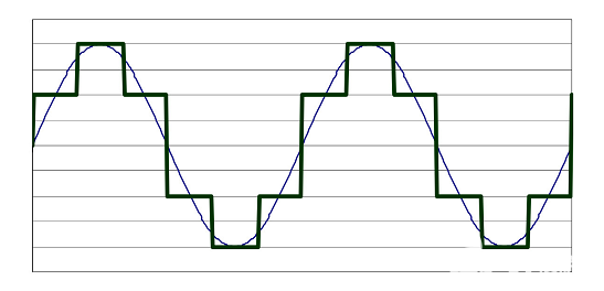
A voltage versus time graph representing how VVI implements AC motor speed control. It is worth noting that if more steps are added, it will better approximate a real sine wave.
2、Pulse Width Modulation
Pulse width modulator circuits or PWMs are a popular method of simulating AC oscillations because they typically provide more precise control than variable voltage inverters. They do this by rapidly switching the current (or “pulsing” it) to match the area under the curve of a true sine wave. Recall from calculus that if the area under the curve of any two consecutive graphs is equal, their integrals are equal; the goal of PWM is to more accurately approximate the area of a sine wave using many voltage pulses, and the density of these pulses will determine the magnitude of the simulated sine wave (and thus change the motor speed). The following graph visualizes these spikes on a graph of voltage versus time.
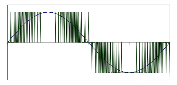
A PWM plot compared to a real sine wave. Note how the pulse changes frequency as it moves along the sine wave, but in an ordered, equally spaced manner.
- Vector Flux
Flux vector drives can change not only the current frequency to change the speed of the motor, but also the torque of the motor. They can do this by using the flux of the motor (the number of magnetic lines of force across the surface, in this case the coil), since a portion of the current in all induction motors must produce a magnetically coupled stator between the rotor and the rotor. The residual current is the portion that generates the torque, and the flux vector drive keeps the coupling current to a minimum while allowing the operator to adjust the current that generates the torque. This is easier said than done, as controlling torque and flux current is analysis intensive and requires continuous translation between coordinate systems.
As a result, flux vector drives require microprocessor-based controllers, software and often coded sensors to precisely regulate independent currents. These drives typically offer speed accuracy of up to 0.3%, which, while more impressive than the other two options, is more expensive to install and operate.