The single-tube AC amplifier circuit with common (emitting) emitter connection is the basic form of triode amplifier circuit.
First, the role of each component in the amplifier circuit
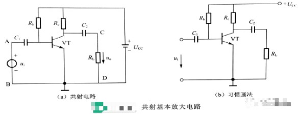
The diagram above shows the basic amplifier circuit with a common (transmitting) emitter connection. The AC signal to be amplified is fed from the input AB and the amplified signal is output from the output CD. The emitter is the common terminal of the input and output circuits, so the circuit is called a common shot amplifier circuit. The role of each component in the circuit is as follows.
1, VT
NPN type triode, the role of amplification, is the core component of the entire amplifier circuit.
2, UCC
DC power supply, the role of two aspects: one is to provide energy for the amplification circuit; the second is to ensure that the transistor is in an amplified state.
3, Rb
Base bias resistor, the power supply through Rb to the transistor emitter junction with a positive bias voltage. In addition, when Ucc certain, by changing Rb can provide a suitable base current IB, the current is usually called bias current, referred to as bias current. Only with the appropriate bias current, the output voltage will not be distorted.
4、RC
Collector resistor, which converts the change of collector current iC into the change of voltage uCE between collector-emitter to achieve voltage amplification.
5、C1、C2
C1, C2 are called the input coupling capacitor and output coupling capacitor, respectively. Using the characteristics of the capacitor to DC impedance infinity, AC impedance is very small, through C1 AC signal coupling to the transistor, while isolating the circuit and the signal source between the direct current circuit; through C2 from the transistor collector to the alternating output signal to the load, while isolating the collector and the direct current circuit between the load. Therefore, the role of C1, C2 is to isolate the DC, through the AC.
In practice, in order to simplify the circuit shown in the above figure (a), the power supply symbol is often omitted when drawing the diagram, only the endpoint of the power supply voltage is drawn and labeled with UCC, which gives the above figure (b).

Second, the current waveform in the amplifier circuit
From the above component introduction, we can initially understand that there is both DC and AC in the amplifier circuit. AC is the change signal that needs to be amplified, and DC is to establish the conditions for amplification.
When the AC signal ui is applied to the amplifier circuit shown below, the waveform of the current and voltage in the circuit and its symbols are explained, taking the base current as an example.
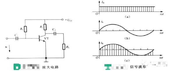
1、DC component
The waveform shown in the figure on the right (a) is the base DC current, which is represented by IB.
2、AC component
The waveform shown in the figure above right (b) is the base AC current, which is expressed by ib.
3、Total variation
The waveform shown in (c) above right is formed by the superposition of AC current and DC current, and the total base current is expressed by iB, i.e. iB=IB+ib.
Third, the operating state of the amplifier circuit
1、Amplifying circuit without signal input
When there is no signal input to the amplifier circuit, only DC currents and voltages are present at various places in the circuit. These DC currents and voltages, IB, IC, IE, UBE, and UCE, are shown in the figure below.
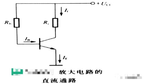
The waveforms of its DC current and voltage are the same as the waveforms shown in the signal waveform diagram (a).
2、Amplification circuit with input signal
When there is an AC signal input at the input of the amplifier circuit, as shown in the figure below.
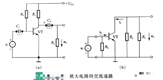
At this time there are AC current components ib, iC, and ie passing through each part of the circuit. If the input signal voltage is ui=Umsin(ωt), the AC waveforms at various places in the circuit are the same as those shown in the signal waveform diagram (b). These AC components are superimposed with the DC component currents when there is no signal input, i.e., UBE, ib, iC, uCE, etc. in the amplifier circuit diagram, respectively. These synthesized actual current waveforms are the same as those shown in the signal waveform diagram (c), which are unidirectional pulsating currents.