Vision is the main way for humans to obtain information about the objective world (it is estimated that 80% of human perception of external information comes from vision), but there are limitations in time, space, sensitivity, spectrum, and resolving power. Optical imaging technology uses various optical imaging systems to obtain objective scenery images, and the visualization of optical information can extend and expand the visual humanity of the human eye.

Since the ancient Egyptians and Mesopotamians first polished quartz crystals to make Nimrud lenses 3,000 years ago, optical imaging technology has continued to develop, from the very beginning of metal photochemical photography, to photochemical photography of photographic plates, to photochemical photography of film, to the emergence of digital cameras, and now the well-known “computational imaging From the beginning of metal photochemical photography, to photochemical photography of photographic plates, to photochemical photography of film, to the emergence of digital cameras, and now to the widely known “computational imaging” (ComputaTIonal imaging) technology, the image scene can be captured not only from near to far, from outside to inside, from meso to macro and micro, and even from there to the other. In the 21st century, internationally renowned research institutions such as Stanford University, MIT, Columbia University, Duke University, University of Southern California, and Microsoft Research have proposed or implemented wavefront-encoded imaging, optical field imaging, time-encoded imaging, aperture-encoded imaging, penetrating scattering medium imaging, etc. based on computational optical imaging [1]. imaging, etc. [1]. In this paper, seven new optical imaging techniques, such as penetrating scattering medium imaging, ghost imaging, markerless optical microscopy imaging, wavefront encoding imaging, single photon scanning imaging, polarization imaging, and holographic imaging, will be introduced for the benefit of image processing enthusiasts.
Penetrating scattering medium imaging
(1) Penetrating scattering medium imaging principle
When light passes through scattering media such as fog, smoke, haze, and turbid seawater, it is affected by the presence of tiny particles in the scattering media, which makes the light scattered, leading to the inability of conventional imaging devices based on light intensity to obtain high-quality images, thus making it difficult to obtain effective information about the scene (scene depth, object material, object surface texture, etc.) [2]. With the in-depth study of scattering medium and scattering properties, an acceptable view is that the scattering medium can be viewed as a linear invariant system, and for a determined random scattering medium, the same input light field always yields the same output light field, i.e., the information carried in the incident light is only cluttered but not lost due to scattering [3]. In other words, the scattering medium only “encodes” the information carried by the light field, and if some special methods can be used to “decode” it, then it is possible to recover the light field before it is scattered, so as to obtain the information carried by it, and penetrate the scattering medium. Media imaging technology was born.
The imaging system through the scattering medium is shown in Figure 1-1. The light carrying the object information is incident on the scattering medium, which propagates randomly inside the scattering medium and the scattering effect occurs, making the propagation direction and phase distribution of the scattered light field appear randomly disordered, and then the scattering pattern with random intensity distribution is shown on the receiving surface of CCD (Charge-Coupled Device), and the scattered image can be reconstructed by suitable calculation to obtain a clear The scattered image can be reconstructed by suitable calculation to obtain a clear image of the target. However, the scatter correlation method is limited by the angular range of the optical memory effect (OME, OpTIcal Memory Effect), and the computational reconstruction is not easy and often requires the setting of a reference point. In view of this, a polarization modulation-based method is proposed in the literature [4] to observe scattering media outside the OME range, and unlike other methods beyond OME imaging, this method can reconstruct the target without a reference point.

At present, the penetrating scattering imaging technology has been able to obtain effective information in the scene in the environment where scattering medium exists, such as scene depth, material material, object surface texture, etc.. Therefore, it is widely used in many fields such as scientific research, industrial production, residential life and social security, such as undersea exploration, navigation, remote sensing, mapping, fire rescue and other practical scenes, where the depth of the scene allows people to judge the shape, size and distance of the target object, providing effective guidance for exploration and rescue.
(2) Example image of penetrating scattering medium
As shown in Figure 1-2, the original target image is shown in Figure 1-2(a), and the scattergrams captured by the camera after passing through the hairy glass, chicken breast, and onion epidermis, respectively, are shown in Figure 1-2(b), and Figure 1-2(c) shows the results of the scattergrams recovered by the basic Fienup-type recovery algorithm after autocorrelation [5].

2. Ghost imaging
(1) Ghost imaging principles and applications
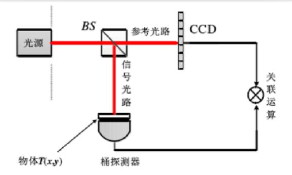
Ghost imaging, also known as correlation imaging and quantum imaging. Ghost imaging uses the quantum entanglement property or the correlation property of light intensity rise and fall to recover an image of an object on a targetless optical path through correlation algorithms. It uses a pair of entangled photons to “break up”, one photon encounters an object and is received by a detector with no spatial resolution, while the other photon is also received by the detector, and the two detectors “meet” to get a picture of the object [6 ]. It is similar to two painters who do not know each other and scribble freely on the canvas with their eyes closed, but collaborate to paint an accurate portrait of a person.
The principle of “ghost imaging” is shown in Figure 2-1. The light source irradiated to the beam splitter is divided into two paths: reference light and signal light, where the reference light is received by the CCD array with spatial resolution, and the signal light is hit into the object T and received by the barrel detector without any spatial resolution, and then the information received from the two paths is used to carry out the recovery operation of the correlation algorithm to obtain the recovery map of the image [7].
At present, quantum imaging includes three major technical routes such as quantum imaging based on entangled light sources, quantum imaging based on classical light sources and quantum imaging with active optical field modulation, while three new techniques, single-pixel imaging, single-photon scanning imaging and non-visual field imaging, have been derived from quantum imaging with active optical field modulation [8]. Recently, the literature [9] proposed computational convolutional ghost imaging (CCGI, ComputaTIonally ConvoluTIonal Ghost Imaging) by redesigning Hadamard-based illumination patterns using convolutional kernels, which not only allows the extraction of features of interest without imaging first, but the CCGI method can also be sub-Nyquist sampling conditions to work adaptively.
The technical characteristics of ghost imaging are that the measured values are not two-dimensional images as observed by the human eye in the traditional sense, and need to be correlated with mask information to be converted into images. In some application scenarios, ghost imaging does not even need to completely reconstruct the image, but only needs to recover certain feature information of the scene, so the technique is very suitable for target detection and classification applications. In addition, its sparse sampling characteristics can greatly reduce the amount of information redundancy in the measured values, which is very suitable for image reconstruction in long-distance transmission. Combining the ghost imaging technique with a variety of imaging modalities can bring new imaging solutions for biomedical imaging, space remote sensing, military countermeasure imaging, autonomous driving, and other fields [10].
(2) Example of ghost imaging
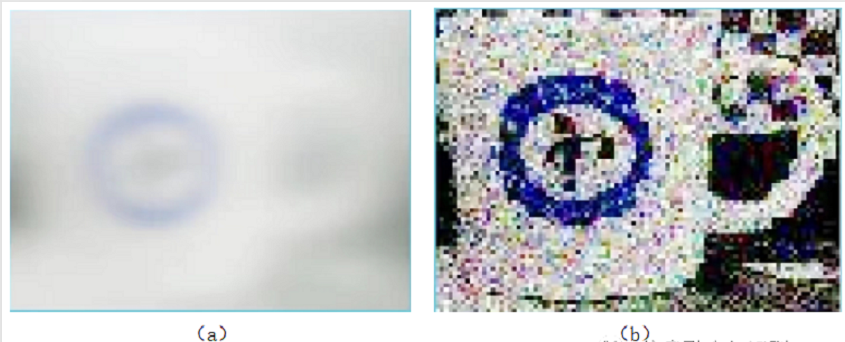
(a) and (b) of Figure 2-2 show the imaging results of conventional imaging and ghost imaging, respectively, when the water cup is blocked by the medium (the medium used here is abrasive paper) [11].
Label-free optical microscopy imaging technology
(1) Principles and applications of label-free optical microscopic imaging
Fluorescence labeling-based microscopic imaging is currently one of the main methods for biomedical imaging, although this technique suffers from bottlenecks such as bleaching, optical bursts, difficulty in specific labeling and fluorescence interference, and therefore, label-free optical microscopic imaging techniques are applied and born. Typical label-free optical microscopic imaging techniques are coherent Raman scattering microscopy, photothermal microscopy, surface equipartition excitation microscopy, and interferometric scattering microscopy [12].
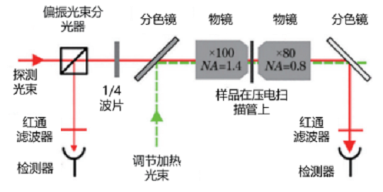
Figure 3-1 shows the schematic diagram of the photothermal microimaging technique. The technique requires the use of two beams of light – a probe laser and a heating laser of frequency Ω obtained through an acousto-optical modulator. First, a large numerical aperture objective (x100, NA=1.4) is used to focus the two beams on the same point of the sample; second, a second objective (x80, NA=0.8) is used to collect the interferometric signals of the emitted and forward scattered fields of the detection laser as the forward signal; then, a combination of a polarizing beam splitter and a 1/4 wave plate is used to collect the interferometric signals of the reflected (reference) and backward scattered fields as the backward Then, the forward or backward signal is collected by the fast light-emitting diode and fed into the lock-in amplifier to detect the differential frequency signal at frequency Ω, extract the photothermal signal, and form the microscopic image.
Since, photothermal microscopy does not depend on fluorescence and is sensitive to absorbed energy, it is able to visualize objects that absorb light, such as metal nanoparticles, endogenous biological components in living cells, etc., as in the literature [13] where the spatial distribution of the chemical composition of polymer samples was obtained using mid-infrared photothermal and Raman microscopy to visualize the chemical composition of co-blended polymer films with submicron scale spatial resolution.
(2) Example of photothermal microscopic imaging
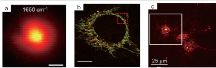
Photothermal micrographs of poxvirus, Hela cells, and oligodendrocytes are shown in (a), (b), and (c) of Figure 3-2, respectively.
Wavefront encoding imaging
(1) Wavefront encoding imaging principles and applications
Wave-Front Coding (WFC) is a hybrid imaging technique that includes both optical design and image restoration, and a superior performance phase mask and powerful restoration algorithms are the keys to the amazing performance of WFC imaging systems [14]. The wavefront-encoded imaging link diagram is shown in Figure 4-1, which gives the optical system the property of being insensitive to image plane defocus by adding an optical phase mask at the exit pupil or aperture diaphragm of the conventional optical system, and the intermediate encoded image obtained within a relatively large thermal defocus range is almost independent of the image plane position [15]. To obtain a clear image, the data encoding processing unit uses digital image recovery techniques to digitally decode and recover the blurred intermediate encoded image, removing the blurred encoding of the optical system imaging by the optical phase plate.
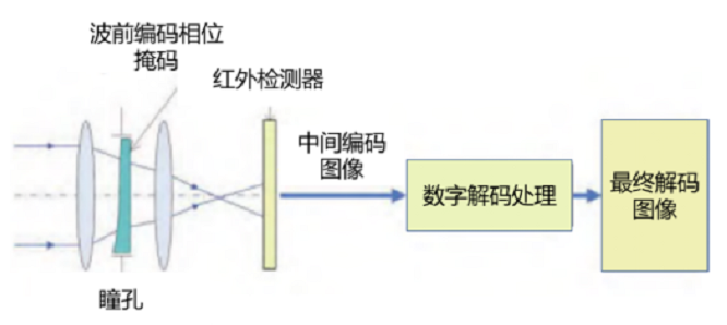
In the literature [14], wavefront-encoded imaging was used to suppress the dynamic Aero-optical Aberration Of Optical Dome (AAOD), thus improving the imaging guidance accuracy when the missile is flying at supersonic speed. The literature [15] illustrates the use of wavefront-encoded imaging to eliminate thermal defocusing due to ambient temperature changes, thus achieving thermal-free imaging of infrared systems.
(2) Example of wavefront-encoded infrared imaging
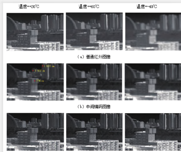
Figure 4-2 shows the imaging results of infrared images (in Figure 4-2 (a)) and wavefront-encoded infrared imaging (in Figure 4-2 (b) and (c) before and after the digital decoding process of wavefront-encoded imaging, respectively) at different temperatures.
Single photon scanning imaging
(1) Single-photon scanning imaging principles and applications
The single-photon detection technology not only enables the detection sensitivity to reach the level of single photon, but also can achieve the time resolution at the picosecond (ps) level, thus, the single-photon technology combines excellent detection performance and distance resolution. The principle frame of photon detection imaging system based on Geiger-mode avalanche photodiode (GM-APD) detector is shown in Figure 5-1 [16]. This technology uses the characteristics of high laser capability density and good directionality, and uses a photodetector with single photon detection capability to obtain a two-dimensional grayscale image of the target through high-precision sampling and inversion calculation of the target light field in time and space; at the same time, the round-trip time and angular position of the laser pulse at the target point are measured to obtain a distance image of the target; after processing the grayscale image and distance image of the target point The 3D image of the target is obtained after processing the grayscale image and the distance image of the target point.

Recently, single-photon imaging technology has been developing at an impressive rate. 1550 nm pulsed lasers and scanning mirrors have been used to perform experiments on active single-photon 3D imaging at a distance of 45 km using a sub-pixel scanning method; in 2021, a long-range 3D single-photon scanning imaging of 201.5 km was achieved. There is also research on combining environmental noise with active intensity images to guide the filling of missing information in depth images, which has achieved remarkable results. In addition, the introduction of high-sensitivity optical detection devices such as single-photon counters in optical remote sensing techniques for receiving some weak backscatter signals has also achieved good results [17,18].
(2) Example of single photon imaging
Figure 5-2 (a) shows the reconstruction results of the active single-photon 3D imaging completed at a distance of 45km using the sub-pixel scanning method, and the 0.6m-wide window on the building is clearly visible in the reconstruction results. Figure 5-2 (b) shows the reconstruction results of the long-range 3D single-photon scanning imaging achieved by the team at 201.5km.

Polarization imaging
(1) Polarization imaging principles and applications
Polarization is one of the important object properties of light, and targets on the surface or in the atmosphere generate specific polarization information determined by their own characteristics when reflecting, scattering, transmitting and radiating electromagnetic waves. Polarization imaging adds the information of polarization dimension to the traditional imaging, which can not only provide the light intensity distribution in two dimensions, but also obtain the polarization information of the target and background, which is very helpful to analyze the shape, surface roughness, texture orientation and physicochemical properties of the target [19]. From the technical route, the existing polarization imaging methods are split-time, split-amplitude, liquid crystal modulated, split-aperture, split-focal plane, and channel modulated, and each type has its own advantages and disadvantages, and the interested reader can refer to the literature [20].
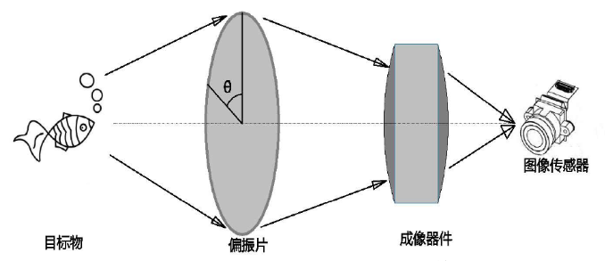
Among them, the commonly used time-sharing polarization system can obtain polarization images of the same scene with different polarization angles in different time periods by moving the device or manually adjusting the polarization angle, such as by rotating the polarizer and waveplate angle to obtain the polarization angle of 0 degrees, 45 degrees, 90 degrees and 135 degrees in four polarization components in turn. As shown in Figure 6-1, the time-divisional polarization imaging system is composed of a polarizer and a waveplate placed behind the objective lens of the imaging system.
In civil applications, polarization imaging can be used for surface loss detection of transparent materials, 3D measurement of highly reflective/radiometric, non-textured targets, rapid identification and classification of metallic and non-metallic targets in complex sites, metal fatigue damage assessment, and medical clinical diagnosis; in military applications, polarization imaging can be used for anti-camouflage, anti-jamming, improved target detection distance, and target classification. Polarization imaging can address the “thermal contrast fade” of infrared detection – the “loss” of target contrast at certain times of the day. In addition, polarization imaging can also be used for underwater target detection, such as detecting other submarines and mines, salvaging and searching for their own human and property [21]. Currently, algorithms to improve the quality of polarization imaging are still an open topic under development [22].
(2) Example of polarization imaging
Polarization imaging can reduce water reflections, glass reflections, and other non-metallic reflections. For example, (a) of Figure 6-2 indicates the effect of a normal camera when no polarizer is added, while (b) of Figure 6-2 shows the effect of a polarized camera [23]. By using a polarizing camera, the saturation of color can be increased, thus restoring more realistic color. As shown in Figure 6-3, (a) is the image taken by a normal camera, while (b) is the image taken by a polarized camera.


Holographic imaging
(1) Holographic imaging principles and applications
The basic principle of holography is that the coherent superposition of light waves reflected from an object and reference light waves produces interference fringes, and these interference fringes are recorded as a hologram, which can reproduce a realistic three-dimensional image of the original object when reproduced under certain conditions. According to the different means of recording and reproduction of holograms, holograms can be divided into optical holograms, computational holograms, and digital holograms [24]. The commonly used digital hologram imaging principle diagram is shown in Figure 7-1, where the light source passes through two beams formed by beam splitting mirrors, one of which is irradiated to the frog, and the light waves reflected by the frog are coherently superimposed with the other reference beam to produce interference fringes, i.e., holograms, which are later received by a CCD (CCD replaces the traditional dry plate used to record holograms), and then the hologram is reproduced by a computer in digital form, and the common The common reconstruction methods are Fresnel transform, convolution, phase shift, and phase recovery.

Combining holographic imaging with other imaging technologies is one of the current development trends. For example, combining holographic imaging technology and microscopy technology, making full use of the advantages of both, not only can magnify the sample object, but also can record the three-dimensional information of the object dynamically; the hologram of the information to be encrypted is used as the secret information embedded in the carrier image to achieve information hiding, and the propagation law and structural geometric parameters are used as the key, and by designing multiple “locks The hologram of the information to be encrypted is used as the secret information embedded in the carrier image to achieve information hiding, and the propagation law and structural geometric parameters are used as the key, and the data encryption with high confidentiality can be achieved by designing multiple “locks” and multiple “keys” [25, 26].
(2) Example of digital holographic imaging
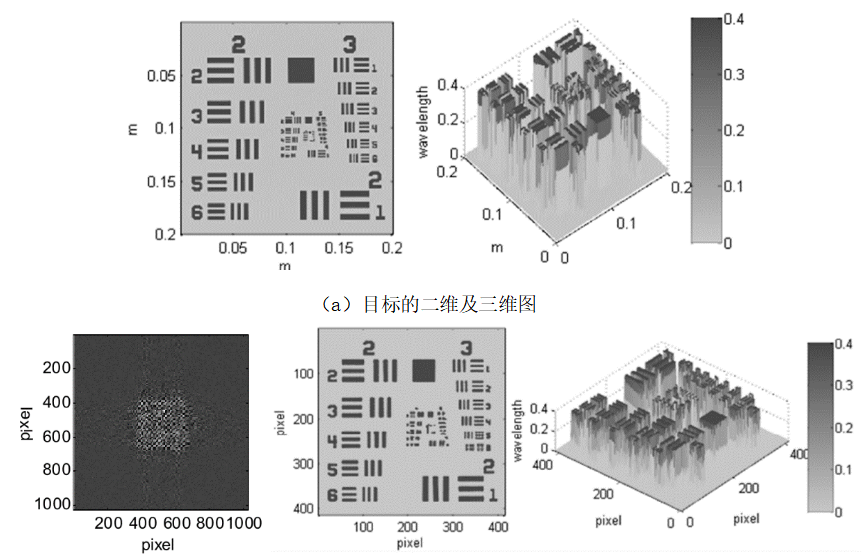
Through Matlab, the simulation model shown in Figure 7-2 is designed, and the hologram of this model is shown in Figure 7-2(b), and the reconstructed two-dimensional and its three-dimensional maps of the target are obtained by the Fresnel transform method as shown in Figure 7-2(c) [27].
In general, the combination of optical detectors, signal processing technologies and new computational optical imaging theories and methods has gradually shown a vivid scene of multiple breakthroughs ready to take off. China has achieved promising results in optical computational imaging theory and technology, and new technologies and applications will certainly give rise to new image processing needs that deserve the attention of image processing researchers.
References