In order to comply with the miniaturization and multi-polarization of 5G communication antennas, the authors propose a multi-channel RF series solution, which includes a circular multi-channel connector, and a shaped multi-channel connector. The said circular multi-channel connector includes a circular socket and circular plug, and the said shaped multi-channel connector includes a shaped socket and shaped plug; the multi-channel connector series of this technology has excellent process manufacturability and fast field installation and maintenance characteristics from the solution and structural design. (Note: this technology has been granted a patent)

I. Overview
The current and the next period, the communications industry is the hot spot is to prepare for 5G. 5G communication system’s best performance, is to achieve the excellent experience of 100Mbps anytime, anywhere, in the initial deployment of 5G, it is necessary to give priority to continuous large bandwidth spectrum, that is, the new 4 × 4MIMO (multiple transceiver multiple transmitter) technology requires more RF units, antennas and other antenna supporting products appear more ports;. Flexible CA (Carrier Aggregation) technology requires equipment to support more frequency bands, therefore, RF coaxial connectors towards miniaturization, as well as integration is the long-term direction of development.
In the mobile communication RF system, RF multi-channel, low frequency multi-channel and mixed frequency multi-channel connectors, in the RF transmission equipment has a unique application advantages; it can be relatively easy to achieve a variety of electrical transmission interconnect port modularity and product serialization, can minimize the installation space of the equipment, can maximize the high effectiveness from manufacturing to application, can maximize the improvement of The internal quality and appearance of communication equipment can be maximized.
However, with the rapid development of mobile communications technology, the current market for multi-channel connectors after several years of application has also revealed the following shortcomings and deficiencies.
1, its socket and plug is generally threaded (or flange screw) connection method, does not support quick plug installation.
2, the components of the contact pair is not disassembled after assembly, not to mention the interchangeable common.
3, its socket and plug manufacturing process is complex, especially after the assembly also needs to be glued encapsulated, so the manufacturing cost is not only high, the quality of its products is also difficult to improve.
II. A multi-channel RF series solution
The purpose of the present technology is to overcome the above-mentioned defects and shortcomings, providing a multi-channel connector series solution.
A multi-channel connector series solution includes a circular multi-channel connector, and a shaped multi-channel connector.
The circular multi-channel connector includes a circular socket and a circular plug, and the shaped multi-channel connector includes a shaped socket and a shaped plug; both the circular multi-channel connector and the shaped multi-channel connector have a one-hand quick plug installation method, where the circular socket in the circular multi-channel connector also supports the one-hand threaded connection installation method.
The circular multi-channel connector and the shaped multi-channel connector include more than two sets of component contact pairs (including high and low frequency and other electrical contact pairs in mixed form) that can be inserted (and separated) from each other; said component contact pairs include a hole assembly and a pin assembly. Said component contact pairs can also be interchangeably and universally assembled within circular multichannel and arbitrary polygonal multichannel connectors.
The multi-channel connector series of this technology has excellent process manufacturability and fast field installation and maintenance characteristics from the scheme and structural design.
See Figure 1: The circular multi-channel connector described, includes a circular socket (110) and a circular plug (210), said circular socket (110) can be installed on the device (000), and other occasions where connection and separation is required.

Fig. 1
Referring to Figure 2: said circular socket (110) includes more than two sets of hole assemblies (111) inside it; said hole assemblies (111) are embedded in a bushing (112); said bushing (112) is provided with axial positioning surface (112d) and radial positioning surface (112e) on each hole inside it. At the same time, the bushing (112) is sealed with the hole assembly (111) by a seal (112b); said bushing (112) is provided inside the circular socket housing (113) with a seal (113a) between the mating surfaces; a main keyway (112a) and a number of secondary keyways (or secondary keys) are provided at the front end of the outer circle of the bushing (112), and on the outside corresponding to the main keyway ( 112a) with directional markings 113h, said subkey slots (or subkeys) being set in an asymmetrical distribution and maintaining the same alignment distribution as the circular plug (210). A flange edge (113b) and a seal (113c) are provided at the outer rear end of said circular socket housing (113), and an external thread (113d) is provided in the middle section, said external thread (113d) being able to support the installation when the circular plug (210) is screwed (01b) connected. Symmetrical two planes 113f are provided on the bottom diameter surface of the male thread (113d) (for installation when 000 with communication equipment). The said circular socket housing (113) is provided with a number of balls (113e) set at its front end and a normalized socket reference surface (1131) designed at its end face. In addition, the circular socket (110) is configured with a flat washer (114), a resilient washer (115) and a nut (116). A seal (113a) is provided on the radial mating surface of the bushing (112) and the round socket housing (113); a gasket (112c) is also provided at the bottom of the hole into which the round socket housing (113) and the round plug housing (212) are inserted.

Fig. 2
Referring to Figure 3: said round plug (210) includes more than two sets of needle assembly (211) inside; said needle assembly (211) is pressed and sealed inside the round plug housing (212) by the multi-hole gasket (211d), multi-hole pressure plate (211e), fastening screw sleeve (211f); said round plug housing (212) is provided with axial positioning surface inside each hole (212e) and radial positioning surface (212f). Said round plug housing (212) is provided with a main key (212a) at the internal front end, and a number of subkeys (or subkey slots), where the subkeys (or subkey slots) are asymmetrically distributed and maintain the same alignment distribution with the socket (110); in said round plug housing (212) is also provided with a directional marker 212c on the outside, while the unlocking sleeve (213) is also provided at the external front section ); a spring (214) is provided inside the unlocking sleeve (213); said round plug housing (212) is provided with a normalized plug reference surface (2121) on its exterior, and a ball groove (212d) is provided in the front section of said plug axial reference surface (2121); a single or multi-threaded external thread (212b) is also provided in its rear section, and in addition the thread (212b) supports the installation of the mounting guard or as a hand-held surface, the equivalent friction angle of its helical sub is designed to be within the safe self-locking angle.
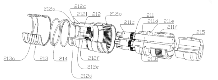
Fig. 3
Referring to Figure 4: The screw sleeve (11) is provided with an internal thread (01a) that matches the external thread (113d) on the circular socket (110) and a stop surface (01b); when the circular multi-channel connector needs to be threaded, the unlocking sleeve (213) on the circular plug (210) and the internal spring (214) are replaced by the screw sleeve (01b). (01b), a threaded connection is achieved; that is to say, the circular socket (110) is compatible with the circular threaded plug.

Fig. 4
See Figure 5: The shaped multi-channel connector described, comprising a shaped socket (01) and a shaped plug (02), said shaped socket (01) can be installed on the device (00) and other occasions where connection and separation is required.

Fig. 5
Referring to Figure 6: said shaped socket (01) includes more than two sets of hole assemblies (111) inside; said hole assemblies (111) are embedded in shaped bushings (010); said shaped bushings (010) are provided with axial positioning surfaces (0106) and radial positioning surfaces (1017); said shaped bushings (010) and hole assemblies (111) are sealed by seals ( 0101); said shaped bushing (010) is provided inside the shaped socket housing (020) with a seal (0102) between the mating surfaces; a mechanical reference surface (0103a) is provided at the outer front end of the shaped bushing (010), and more than one directional convex surface (or directional concave surface 0103) is provided inside; an orientation mark 021 is provided on the opposite side of the directional convex surface (or directional concave surface 0103); said directional mark 021 is provided externally; said directional mark (021) is kept in the same alignment distribution as the directional mark (0301) on the shaped plug (02). A flange edge (022) and a seal (0105) are provided at the rear end of said shaped socket housing (113) exterior; a number of balls (0104) are also provided at the front end. In addition, a gasket (0108) is provided at the bottom end where the shaped socket housing (020) is inserted with the shaped plug housing (0500).

Fig. 6
Referring to Figure 7: said shaped plug (02) includes more than two sets of pin assemblies (211) inside it; said pin assemblies (211) are pressed and sealed inside the shaped plug housing (0500) by hole gaskets (0211d), hole pressure plates (0211e), fastening screw sleeve (0211f); each hole inside said shaped plug housing (0500) is provided with axial The said shaped plug housing (0500) is provided with axial positioning surface (0503) and radial positioning surface (0504) inside each hole. The shaped plug housing (0500) is provided with a directional concave surface (or directional convex surface 0505) at the front end; a shaped unlocking sleeve (0300) is provided outside the shaped plug housing (0500); a shaped spring (0400) is provided inside the shaped unlocking sleeve (0300); a shaped stop edge (0502) is also provided outside the shaped plug housing (0500), a shaped plug (0507) and shaped ball groove (0501); inside the shaped unlocking sleeve (0300) there is a stop ring (0302) designed at the rear end and outside the shaped unlocking sleeve (0300) there is a direction mark (0301), said direction mark (0301) keeps the same alignment distribution with the direction mark (021) on the shaped socket (01).

Figure 7
See Figure 8: Said hole assembly (111) includes a cable (111a) and a hole contact head (111b), said hole contact head (111b) includes an inner hole conductor (111ba), an outer hole conductor (111bb), a hole insulation sleeve (111bc), an outer bushing (111bf), a cable retaining sleeve (111be), an outer seal (111bh), an inner seal ( 111bg). Also provided on said outer conductor (111bb) are axial positioning (111bba) and radial positioning (111bbc), and electrical contact surfaces (111bbd). A slotted resilient hole (111baa) is provided in said inner conductor (111ba).

Fig. 8
Referring to Figure 9: said needle assembly (211) includes a cable (211b) and a needle contact head (211c), said needle contact head (211c) includes a needle inner conductor (211ca), a needle outer conductor (211cb), a needle insulating sleeve (211cc); on said needle outer conductor (211cb) are also provided axial positioning (211cd) and radial positioning ( 211cg), and an electrical contact surface (211ce). On said needle outer conductor (211cb) is a slotted elastomer (211cf).

Figure 9
Interconnection and separation operation of sockets and plugs and electrical contact mechanism of this technical product
1, round socket (110) and round plug (210) of the interconnection and electrical contact mechanism
Hold the round plug shell (212) on the round plug (210) with one hand, and make the directional mark (212c) on the round plug (210) and the round socket (110) on the mark (113h) approximately aligned, while inserted; at this time, the introduction surface (212c) on the round plug shell (212) will be the ball (113e) top open, and the ball (113e) randomly will also be unlocking sleeve (213) against, at which time the spring (214) is compressed; as the round plug (210) continues to be inserted, when the socket reference surface (1131) coincides with the plug reference surface (2121), then the ball slot (212d) on the round plug (210) also reaches the position of the ball (113e) on the round socket (110); and the ball (113e) is compressed by the spring ( 214) force through the unlocking sleeve (213) on the tightening surface (213a) to hoop a number of balls (113e) in the ball groove (212d); thus, the round plug (210) and the round socket (110) to achieve a quick connection and locking. The hole assembly (111) and the needle assembly (211) of each of these channels, through the hole contact head (111b) and the needle contact head (211c) also achieve a good electrical contact.
2. Separation of circular socket (110) and circular plug (210)
The separation of the round socket (110) and the round plug (210) requires only one hand to hold the unlocking sleeve (213) on the round plug (210) with one hand and pull it back.
3, shaped socket (01) and shaped plug (02) of the interconnection and electrical contact mechanism
Hold the alien plug (02) on the alien plug shell (0500) with one hand, and make the alien plug (02) on the direction mark (0301) and the alien socket (01) on the mark (021) approximately aligned, while inserted; at this time the alien plug shell (0500) on the introduction surface (0506) will be the ball (0104) top open, and the ball (0104) randomly will also be alien unlocking sleeve (0300) against, at which time the shaped spring (0400) is compressed; as the shaped plug (02) continues to be inserted, when the shaped socket reference surface (0103a) coincides with the shaped plug reference surface (0507), then the shaped ball slot (0501) on the shaped plug (02) also reaches the position of the ball (0104) on the shaped socket (01); and the ball ( 0104) then hoops a number of balls (0104) in the shaped ball slot (0501) through the tightening surface inside the shaped unlocking sleeve (0300) under the force of the shaped spring (0400); thus, the shaped plug (02) and the shaped socket (01) are quickly connected and locked. Wherein the hole assembly (111) and the needle assembly (211) of each channel, good electrical contact is also achieved by the hole contact head (111b) and the needle contact head (211c).
III. Beneficial effects of the present technical solution
1, the technology of the component contact pairs, the outer conductor (electrical connection interface) preferred radial elastic surface contact design, so that the pressure between the contact is constant in an effective interval; and no longer subject to environmental or artificial external forces (three-dimensional and alternating vibration and shock), the most fully reduced (or eliminated) each component contact pairs electrical even contact, the occurrence of non-linear contact (or instantaneous), thereby reducing (or eliminating) (or eliminate) the generation of electrical contact interference sources; solves the stability of the static and dynamic electrical performance of each channel electrical connection port.
2, the technology of each component contact pair, its removable and separated preferential design, as well as the design of each channel mechanical reference plane normalization; so that the RF impedance to get the best compensation, the most fully maintain the impedance continuity of the RF channel; at the same time, so that the socket and plug connection to ensure the consistency of the electrical length of each channel; therefore, this technology has a wider RF bandwidth and lower return loss characteristics; and more Smaller phase difference. At the same time, for the mass production inspection process, as well as the maintenance and repair of the equipment system to create simple and convenient conditions.
3, the preferred design of the ball mechanism locking and unlocking, so that its circular multi-channel connector and shaped multi-channel connector, more easily and reliably achieve the function of fast insertion and fast separation, and the circular multi-channel connector in the circular socket is a dual function of fast insertion and threaded connection. The said quick plug connection requires only one hand operation can easily achieve a reliable electrical connection of multiple channels.
4, the technology key and key slot asymmetric preferred design, to achieve the blind plugging function, to ensure that each channel components contact pairs of interchangeable interconnections, based on anti-misplacing and anti-misplacing and adaptive alignment characteristics.
5, the technology of the socket to take a triple seal preferred design, taking full account of the socket in the communications equipment port application when the plug is not installed, the environment of moisture and other harmful gases on the internal erosion of communications equipment; and the plug to take a double seal setting; therefore, the products of this technology has a strong environmental performance.
6, in summary: the technology preferred multi-channel radial elastic surface contact design, normalized mechanical reference design, the design of each channel removable separation, fast plug blind plug adaptive alignment design, multiple waterproof sealing and other innovative design; solve the existing similar products exist some defects and deficiencies. It has better electrical performance index; has a wider working band; has the dual characteristics of quick-plug connection and and threaded connection, therefore, has higher product quality, has lower comprehensive cost, and excellent process manufacturability and application convenience.