Logic gates are fundamental building blocks of digital circuits that perform basic logical operations on one or more input signals to produce an output. Logic gates ICs integrate multiple gates together into a single integrated circuit package. They provide the elementary digital functions needed to implement all digital logic systems.
This article provides an overview of logic gates ICs, examining the different types of logic gates, IC advantages, gate-level vs system-level design, logic families, interface considerations, common logic IC part numbers, usage in circuits, and frequently asked questions.
What is a Logic Gate?
A logic gate is an elementary digital circuit that performs logical operations on one or more binary inputs to produce a single binary output. The output is determined based on the selected logical function of the gate.
Some common single-bit logic gates:
- AND Gate – Output is HIGH only if all inputs are HIGH.
- OR Gate – Output is HIGH if any input is HIGH.
- NOT Gate – Inverts the input value.
- NAND Gate – AND function with inverted output.
- NOR Gate – OR function with inverted output.
- XOR Gate – Output HIGH only if inputs differ.
- XNOR Gate – XOR function with inverted output.
Logic gates with more inputs are also available like 4-input AND gates. Gates can also be cascaded to form more complex logic.
What is a Logic Gates IC?
A logic gates IC houses multiple logic gates of various types within a single integrated circuit package. Some examples:
- Quad 2-input NAND gate IC
- Hex inverter IC with 6 NOT gates
- Dual 4-input AND gate IC
- Octal buffer containing 8 non-inverting buffers
- 4-bit XOR logic IC
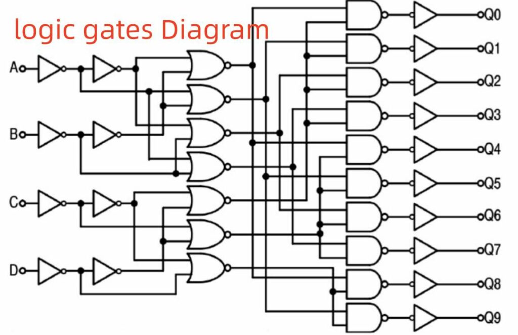
Logic ICs integrate the gates needed to implement small logic functions. Hundreds of gates are then combined on ICs like FPGAs to realize complex digital systems.
Advantages of Using Logic Gates ICs
Key benefits provided by logic gate ICs:
- Integration – Many gates packaged together in one IC.
- Smaller Size – Miniaturized construction vs discrete gates.
- Lower Cost – Cheaper than individual logic gates.
- Simplified Design – Requires less PCB space and routing.
- Consistent Logic – Matched gate timing on one IC.
- Lower Power – Optimized for low power consumption.
- Standard Functions – Common gates pre-designed for convenience.
- Interchangeability – Easily swap gate types if needed.
In most cases, logic ICs are preferred over discrete logic gates.
Gate-Level vs System-Level Design
Two basic approaches are used for digital logic design:
Gate-Level Design
- Focus on individual gates, their arrangements and interconnect
- Manual layout or schematic capture for gate logic
- Select appropriate logic ICs to implement schematic
System-Level Design
- Abstracted function-block modeling
- Top-down register-transfer or algorithmic modeling
- Hardware description languages like VHDL or Verilog
- Synthesis tool outputs netlist targeting technology library
While modern digital design has moved to system-level, understanding gate-level implementation is still important. Logic gate ICs form the fundamental hardware building blocks.
Types of Logic Gates
Several basic single-bit logic gates are commonly provided within gate ICs:
AND Gate
The AND gate outputs HIGH (1) only when all inputs are HIGH (1). If any input is LOW (0), the output is LOW (0):
OR Gate
The OR gate outputs HIGH (1) if any of the inputs are HIGH (1). The output is only LOW (0) when all inputs are LOW (0).
NOT Gate
The NOT gate inverts the logic value of the single input. HIGH input results in LOW output. LOW input gives HIGH output. Also called an inverter.
NAND Gate
This gate implements an AND function with the output inverted. Output is LOW with all HIGH inputs. HIGH in other cases.
NOR Gate
The NOR gate gives the inverted OR logic function. Output is HIGH only if all inputs are LOW. LOW in other cases.
XOR Gate
Outputs HIGH when the number of HIGH inputs is odd (one or both). LOW when input states are the same (both HIGH or both LOW).
XNOR Gate
XNOR inverts the output of the XOR function. HIGH when inputs match. LOW when different.
Other additional logic gates like 3-input AND, 4-to-1 MUX, and larger bit-size versions are also available.
Logic Gate Symbols
Each logic gate type has a distinctive circuit symbol to enable schematic design. Some common examples:
Learning to quickly recognize logic gates from their symbols is essential for reading and designing digital schematics.
Logic IC Families
Several logic IC families exist with different characteristics:
TTL (Transistor-Transistor Logic)
The original bipolar transistor logic family. Robust drive with 5V standard voltage. Fast, mature, low cost but higher power consumption. 74xx series TTL is ubiquitous.
CMOS (Complementary Metal Oxide Semiconductor)
Low power consumption but higher propagation delay than TTL. Wider voltage range operation. High input impedance. Most modern logic ICs use CMOS. 4000 series CMOS is common.
ECL (Emitter-Coupled Logic)
Provides very high speed but consumes significant power. Uses an emitter-coupled pair differential amplifier as the basic logic gate. Gain stages allow large cascaded circuits.
NMOS (N-channel MOS)
Early unipolar silicon gate technology. Very small design with high density. More temperature sensitive than CMOS. Mostly replaced today. Used in early microprocessors.
PMOS (P-channel MOS)
Originally used for early microprocessors along with NMOS. Higher power consumption than CMOS. Also largely obsolete today.
GaAs (Gallium Arsenide)
Gallium arsenide semiconductor gives ultra high speed at much higher cost. Low voltage logic with high frequency clock rates reaching ~1GHz. Used in specialized applications.
CMOS provides the best combination of speed, power, density and cost for most contemporary logic.
Open Collector Logic Gates
Open collector or open drain logic gates contain an output transistor without a pull-up resistor connected to the positive rail. This allows multiple gates to share a wired-OR style output connection if required. The outputs float high when disconnected. Also enables wired-AND logic with pull-up resistor. Available for gates like 7406 (hex open collector inverters).
Tri-State Logic Gates
Tri-state logic gates have three output states: HIGH, LOW and HIGH-Z (high impedance). The HIGH-Z state electrically disconnects that gate’s output from the net allowing multiple gate outputs to share a common bus or I/O pin – essentially behaving like an electronic switch. Available for gates like 74126 (Quad tri-state buffers).
Schmitt Trigger Logic Gates
These logic gates contain an analog comparator front-end that provides hysteresis on the input threshold voltage. This makes the gate more immune to input voltage noise ensuring clean logic level switching. They help remove issues with slowly slewing inputs getting stuck in the linear undefined region between valid logic HIGH and LOW voltage levels. Hex schmitt trigger inverters like 74HC14 provide this behavior.
Unused Gate Inputs
When logic gates within ICs are unused, the unused gate inputs must be terminated properly to avoid issues:
- Unconnected CMOS inputs should be tied to VCC or ground.
- Unused TTL inputs can float but may cause higher power consumption.
- Tying unused gates together simplifies termination.
Check IC datasheets for recommended termination of unused inputs.
Interfacing Different Logic Families
When interfacing between different logic families like CMOS and TTL:
- Verify voltage levels are compatible between output and input.
- Check output sink/source current drive capacity is sufficient for the input.
- Insert level shifting circuits if voltages are incompatible.
- Limit output rise/fall time slew rates to prevent noisy switching.
- Use gates with schmitt trigger inputs for robustness.
Careful interface design prevents reliability issues or undefined operation.
Common Logic IC Part Numbers
Some examples of standard logic ICs with common part numbers:
- 7400 – Quad 2 input NAND gate
- 7402 – Quad 2 input NOR gate
- 7404 – Hex Inverter (NOT gate)
- 7408 – Quad 2 input AND gate
- 7432 – Quad 2 input OR gate
- 7486 – Quad 2 input XOR gate
- 74138 – 3 to 8 line Decoder
- 74157 – Quad 2 line to 1 line Multiplexer
- 74157 – Quad 2 input Multiplexer
- 74259 – 8 bit Addressable Latch
- 74373 – Octal Transparent Latch
- 7476 – Dual JK Flip Flop with Clear
- 74153 – Dual 4 line to 1 line Multiplexer
- 74244 – Octal Buffer with tri-state outputs
There are hundreds of logic ICs available with different gate types, counts and combinations. Consult datasheets for full specifications.
Usage of Logic Gates in Digital Circuits
Logic gates are the basic building blocks used extensively in all digital electronic systems:
- Combinatorial logic using gates for Boolean logic, encoders, decoders, multiplexers, arithmetic circuits.
- Sequential logic utilizing gates to construct flip flops, registers, counters, sequencers, state machines.
- Memory circuits using gates for SRAM, DRAM, CAM, and other memory cell design.
- Microprocessor and computer architectures requiring logic for ALUs, control units, buses, registers, timing.
- Peripheral device controllers leveraging logic gates for I/O.
- Gate arrays, CPLDs and FPGA chips using vast quantities of gates.
- Bit slice architectures build from modular 4-bit gate sets.
- Feed forward neural networks constructed from layers of logic gates.
All aspects of digital design require logic gates.
Summary
- Logic gates provide elementary digital logic operations on binary signals.
- Gate ICs integrate multiple gates into single, convenient packages.
- AND, OR, NOT, NAND, NOR gates provide basic Boolean logic functions.
- Gates connect together to build complex combinatorial and sequential logic circuits.
- Logic families like TTL and CMOS have tradeoffs between speed, power, density.
- Unused gates inputs require proper termination for robust operation.
- Logic ICs enable fast, economical realization of all digital systems.
Understanding these fundamental building blocks is key to implementing both simple and highly advanced logic circuits and computer architectures.
Frequently Asked Questions
What is the primary advantage of CMOS logic technology over TTL?
CMOS logic consumes much lower static power than TTL. Its high input impedance also reduces power consumption while TTL inputs draw more current. Lower power gives CMOS chips higher density and lesser heating.
What is a pull-up resistor and when is it required?
A pull-up resistor connects the gate output to the positive supply voltage. This establishes a known logic HIGH level when the output transistor is open. Pull-ups are required for interfacing open-collector TTL or open-drain MOS logic outputs.
How can different logic families be interfaced when voltage levels don’t match?
A simple two-resistor voltage divider circuit will translate between mismatched high and low logic levels when interfacing different families like TTL and CMOS. This serves as a level shifting interface.
What are some key differences between combinatorial and sequential logic?
Combinatorial logic output depends solely on the present inputs whereas sequential logic depends on past inputs and prior states stored in memory. Sequential circuits require memory elements like flip flops while combinatorial circuits do not.
When should transmission gate logic be used instead of normal gates?
Transmission gates allow bidirectional signal flow and have very low input impedance unlike regular gates. They are used when signals must pass in both directions without distortion such as in switch matrices or bus drivers.