/ Introduction /
Successful self-driving cars will certainly use tightly integrated sensor systems to meet or exceed human driving capabilities. Human drivers typically use both eyes, both ears, and the feedback given to them by the vehicle’s motion to drive the car. Our brains process all of this information in real time and react intuitively from the human brain’s database of driving experience. The sensors needed to replicate the human driving ability include radar, lidar (LIDAR), cameras, inertial measurement units (IMUs), and ultrasonic sensors. Each of these systems has its advantages and disadvantages. There is a general trend towards multi-sensor fusion where the accuracy and performance of a single sensor is not sufficient to replace all other sensors complementing each other. This paper will present the main design considerations related to the LIDAR, a sensor that provides a large amount of data for various autonomous driving solutions..

Figure 1. Spider web diagram comparing visual, radar and LIDAR.
Content.

In self-driving cars, LIDAR works closely with radar. Both technologies operate without producing visible light, which is critical for night driving or low-light conditions. While radar is suitable for long-range detection and tracking, LIDAR offers higher angular resolution to identify and classify objects. In other words, while radar is suitable for detecting the presence or absence of an object, LIDAR is able to provide specific information about the object based on its detection by radar.
There are a number of technical challenges in designing LIDAR systems, one of the main ones being to keep the NIR wavelengths below the safety limits for the human eye. This is not to diminish the importance of human eye safety, as all of the aspects discussed in this paper ultimately impact human eye safety. A variety of different LIDAR system technologies exist, with varying degrees of design complexity, each with its own advantages and disadvantages.
Importantly, all designs need to focus on the same fundamental aspects. Here again we focus on aspects other than human eye safety that affect system design, including: SNR maximization, minimum detectable requirements, field of view, heat dissipation, power consumption, and aerial position speculation.
A look at the receive link reveals that the signal-to-noise ratio (SNR) of the system affects the ability to detect small targets at long distances (100 m to 300 m.) The ADC noise floor cannot exceed other noise sources in the receive path. If the background light or scattered particle noise contributors are lower than the ADC noise floor or printed circuit board (PCB) noise, the system accuracy is limited. The use of the direct time-of-flight (ToF) method requires that the system can output short pulses (~1ns to 5ns) and use a high sampling rate ADC to detect these pulses. A sampling rate of 1GSPS is sufficient to meet the requirements of the received signal link. Also, note that the effective number of bits (ENOB) of the ADC must support the entire output range of the transimpedance amplifier (TIA), and no clipping of the signal can be applied.
Does the system need to detect a basketball 100 meters away? Determining the reflectivity, size and distance of the object of interest will determine the SNR requirements for the TIA. As with ADC, TIA needs to detect the same narrow pulses. Because the system needs to deal with a wide range of distances, reflectivities and sizes of objects, the TIA must be able to recover quickly after saturation. High reflection (such as traffic signs fear love) or close targets can reflect strong light and cause TIA saturation. These are common events, and the speed of system recovery (to minimize blinding time) is critical to safety.
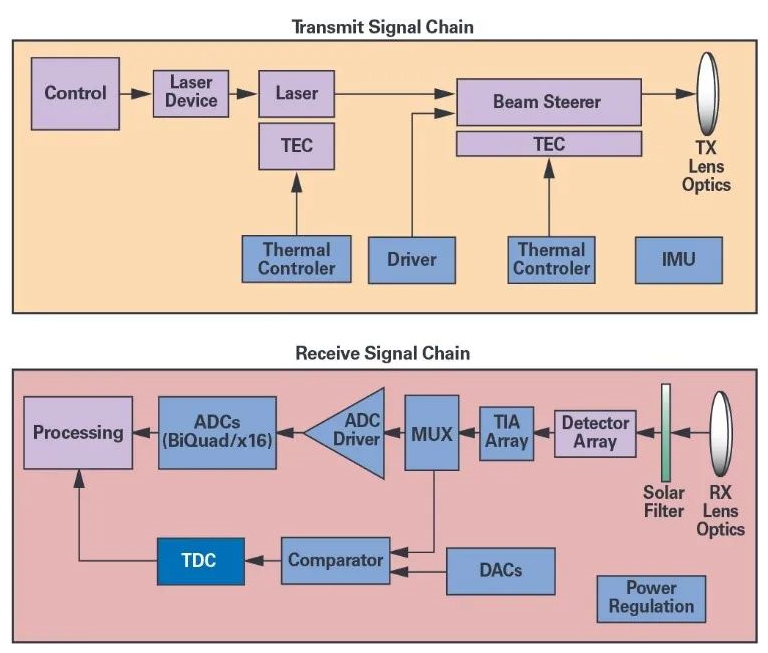
Figure 2. LIDAR electrical architecture.
The field of view and angular resolution of the system also affects the ability to detect a basketball. The transmitting and receiving optics are the primary determinants of the field of view. Angular resolution determines whether you can detect and classify a basketball-sized target at a distance or only detect the presence of a target.
For LIDAR system designers, dealing with the power consumption and heat dissipation of these systems is no small challenge. Of course, reducing the power consumption of the signal chain will correspondingly reduce the heat generated. The performance of components in can vary dramatically with temperature, and some of the more sensitive components may require temperature compensation. Using a thermoelectric controller is a good way to cool or heat the IC with a high degree of accuracy. If accuracy is sought, both light emitting and photodiodes require temperature compensation to maintain a stable operating wavelength and efficiency over the operating temperature range of the LIDAR system.
In some cases, the bias voltages applied to photodiodes and lasers go into the hundreds of volts (positive or negative). Generating these voltages efficiently and using as few components as possible is what best design practices are looking for. To provide an accurate reference voltage source, a precision digital-to-analog converter (DAC) is required to generate the bias point, current and voltage. Along the traditional 1.8V to 12V voltage domain, the voltage requirements of LIDAR systems are increased. Careful selection of power supply solutions can handle this, especially when an additional voltage is added to the solution. It is also important to choose ICs and power supplies with shutdown or low power modes so that the system can be flexible and energy efficient in polling multiple channels.
IMUs with integrated LIDAR sensors offer a variety of advantages. IMU sensors intelligently fuse multi-axis gyroscopes and accelerometers to provide reliable position and motion recognition for de-vibration and navigation applications. Even when faced with extreme motion dynamics in complex operating environments, the precision microelectromechanical systems (MEMS) IMU provides the accuracy required.
The IMU provides position estimation, positioning and stabilization functions for autonomous driving systems. The IMU can effectively utilize high update rates (thousands of samples per second) and can be uninterrupted by external environmental changes. the more stable the IMU is, the longer it can provide critical and reliable track information to the system.
The IMU can be integrated directly into the LIDAR module to detect, analyze and correct for vibrations common in the vehicle operating environment. For example, the IMU output can assist in stitching together LIDAR point clouds that would otherwise be out of alignment as the vehicle crosses potholes in the roadway. In addition, IMU can be used to detect bearing wear in rotating LIDAR systems to repair LIDARs before they actually fail and improve safety.
Conclusion
During initial product definition, the complexity of the LIDAR system needs to be considered to determine acceptable SNR, detection requirements, field of view, thermal limitations, and power consumption. Understanding which components are the primary contributors to each issue, along with careful IC selection, can greatly improve the chances of design success.