Through the microcontroller control peripheral devices (LED, buzzer, digital tube, button), is essentially for the operation of the microcontroller IO port, compared to the STM32, 51 microcontroller IO port mode less, but understand the internal IO for learning to understand the 51 microcontroller also by a great help.

GPIO
GPIO(General Purpose Input Output), General Purpose Input Output. It can be used as both an input and an output port. A port, which is a pin on a component. It can be controlled by software.
In most of the time, we can see the IO port as an electronic switch, by writing the corresponding value into the IO register, the level of its output changes with the register, which is the output of the IO port, in most of the microcontrollers, you need to go to configure the IO mode of the microcontroller, whether it is input or output.
In most microcontrollers, you need to configure the IO mode of the microcontroller, whether it is input or output. i.e. you need to pre-initialize and configure the parameters of the GPIO before using the GPIO. in 51 microcontrollers, such operation is not supported, i.e. you cannot configure the parameters of the GPIO.
51GPIO
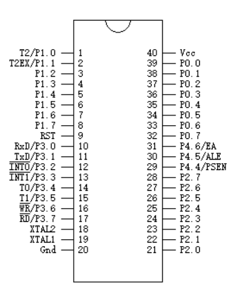
P1/P2/P3/P4 are in quasi-bidirectional port/weak pull-up (traditional 8051 /0 port) mode after power-on reset, except for the special pin of P3. P3 can be used for the second function by configuring other registers.
P0 port is open-drain output after power-on reset and cannot output high level, but if pull-up resistor is connected on output, level conversion is possible and the driving capability is strong. When the P0 port is used as an address/data multiplex bus, no external pull-up resistor (rarely, rarely used) to learn microcontroller, you need to buy devices can go to the only kind of mall, students and what have a discount.
Quasi-bidirectional
The quasi-bidirectional port output type can be used as an output and input function without reconfiguring the port output state, and its power-on reset default level is high.
When the port input is 1, its drive capability is extremely low, allowing it to be pulled low externally. For example, a keystroke. When the output is low, the drive capability is very high and can absorb considerable current. Therefore a keypad design with a high to low conversion is used.
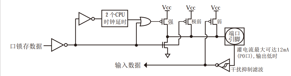
The design uses three pull-up transistors to adapt to different needs. Among the three pull-up transistors, there is one pull-up transistor called “weak pull-up”, which turns on when the port register is 1 and the pin itself is also
is turned on when the port register is 1 and the pin itself is 1. This pull-up provides the basic drive current to enable the quasi-bidirectional port output to be 1.
If a pin output is 1 and is pulled down to low by an external device, the weak pull-up is turned off and the “very weak pull-up” remains on. In order to pull this pin strongly low, the external device must have sufficient current capability to drop the voltage on the pin below the threshold voltage.
The second pull-up transistor, called the “very weak pull-up”, is turned on when the port is latched to 1. This very weak pull-up source generates a very weak pull-up current to pull the pin up to high when the pin is left open.
The third pull-up transistor is called a “strong pull-up”. This pull-up is used to speed up the transition from logic 0 to logic 1 on quasi-bidirectional ports when the port latch jumps from 0 to 1. When this happens, the strong pull-up is turned on for about 2 clocks to allow the pin to be pulled up to high quickly.
The quasi-bidirectional IO port needs to write 1 first when reading the external state in order to read the correct external state correctly.
Open-drain output
When p0 output 1, due to the internal structure, only high resistance state can be output, need to add 10K-4.7K pull-up resistor to output properly. When the port latch is 0, the open-drain output turns off all pull-up transistors.
If there is an external pull-up resistor, the open-drain I0 port can also read the external state, i.e., the I/0 port configured as open-drain mode can also be used as an input I/0 port at this time. The pull-down in this way is the same as the quasi-bidirectional port.
Ps: the following is (STC89C52RC) data sheet provides some reference on the digital tube circuit, learning microcontroller, need to buy devices can go to the only kind of mall, students and what have a discount.
