In the previous article, we talked about the difference between half-wave rectification and full-wave rectification, so we can see that although AC is rectified into DC, this is a pulsating DC.
However, this is a pulsating DC, whereas in practice most applications require a stable DC (with low voltage fluctuations).
Can this problem be solved by using the charging and discharging properties of the capacitor and the power storage function. Let’s use simulation software to find out.
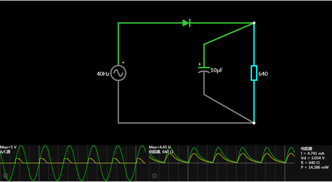
Firstly, the half-wave rectifier is used and the capacitor is added after the rectifier. It was found that it did not achieve the desired purpose. Is the capacitor capacity not large enough. Then we can try again.
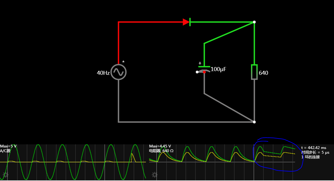
After increasing the capacitor to 100uF, there is an improvement, but still not the intended goal, then continue to try increasing the capacitance of the capacitor.
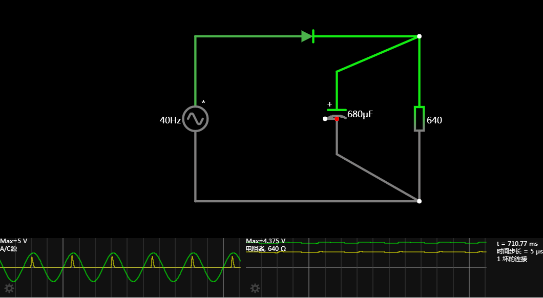
Then increase the capacitance of the filter capacitor to 680uF and you can see that the waveform now basically meets the requirements and can achieve the intended effect.

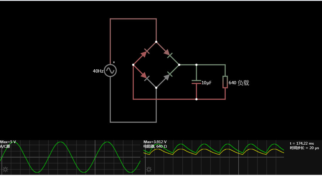
Will it be the same for the full wave rectifier? Let’s continue with the simulation to see the results. Make a comparison.
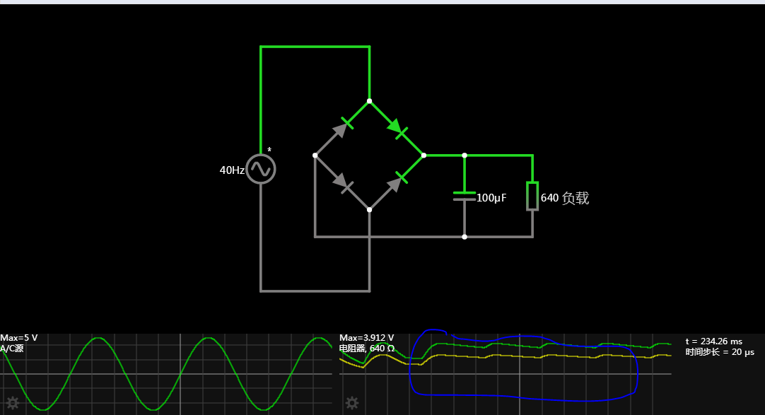
With the same load and the same capacitance and worth of filter capacitors, the final voltage waveform is slightly better than the half-wave, so let’s continue the simulation with more capacitors.
After increasing the filter capacitor to 100uF, we can find that the capacitance waveform obtained can already meet our requirements and achieve the desired effect. Why is the difference so big? With this question in mind, we continue to increase the capacitance value to see.
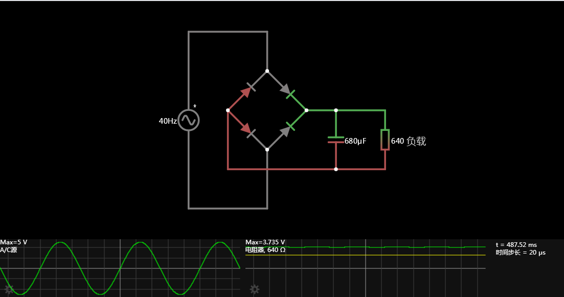
After increasing to 680uF, the output voltage is already very stable, fluctuations are relatively small, and the output current (yellow line) basically has little change and stays at a value (within the allowed deviation).
Why is there a difference in the results obtained when the same filter capacitor is added after half-wave rectification and full-wave rectification? This is because half-wave rectification of the entire cycle only half-cycle energy to the rear stage, only in this half-cycle a section (the front AC value – secondary tube voltage drop > voltage on the capacitor), the capacitor has the opportunity to charge, as long as not on, the rear circuit are required to discharge the capacitor, capacitor discharge energy is not enough, the rear voltage is unstable. Half rectifier circuit, the capacitor in the whole cycle, the capacitor discharge time is greater than half a cycle.
For the full wave rectification positive and negative half-cycle, the capacitor has the opportunity to charge, the front stage has no current over, only when the capacitor is discharged, this time the capacitor discharge cycle is to be less than half a cycle, so to achieve the same effect, the required capacitance value is relatively small.
Translated with www.DeepL.com/Translator (free version)