CAN stands for Controller Area Network (hereinafter referred to as CAN), which is designed to efficiently handle large numbers of messages with minimal CPU load. The CAN communication protocol for automobiles was developed in 1986 by the German electrician BOSCH. Since then, CAN has been standardized through ISO 11898 and ISO 11519, and is now the standard protocol for automotive networks in Europe. Nowadays, CAN is recognized for its high performance and reliability, and is widely used in industrial automation, ships, medical equipment, industrial equipment, etc.
CAN protocol features.

Multi-Master Control.
When the bus is idle, all nodes can send messages. If two or more nodes start sending messages at the same time, the bus will arbitrate according to the Identifier (hereinafter referred to as ID), the smaller the ID, the higher the priority, the better the arbitration, the node that wins the arbitration continues to send, and the node that loses the arbitration immediately moves to the receiving state. Note that the ID does not indicate the node address, but rather the priority of the message sent.
System flexibility.
As mentioned above, there is no information similar to an “address” for each node of the CAN bus. Therefore, when adding or removing nodes from the bus, the hardware and software design of the other nodes connected to the bus is not affected.
High Reliability.
The CAN protocol has error detection, error notification, fault closure and error recovery. Any node on the CAN bus can detect errors (error detection); after detecting an error, it sends an error frame to the bus to notify other nodes (error notification); at the same time, each node has an internal error counting function, and after each error is detected, the error count value is accumulated. other nodes (fault closure). And if the sending node detects an error in the process of sending a message, it will automatically resend the message after the error is over until it is successfully sent (error recovery).
Fast communication speed and long communication distance.
Up to 1Mbps (distance less than 40m) and up to 10km (rate less than 5Kbps).
Multiple connectable nodes.
CAN bus is able to connect multiple nodes at the same time. There is no limit to the number of nodes in theory. However, in practice, the number of nodes is limited by the bus time delay and electrical load. Decreasing the communication speed increases the number of nodes that can be connected; increasing the communication speed decreases the number of nodes that can be connected.
It is these characteristics of the CAN protocol that make CAN particularly suitable for the interconnection of industrial process monitoring equipment, and therefore, it is increasingly valued by industry and has been recognized as one of the most promising fieldbuses. The CAN protocol has been standardized by ISO with two standards: ISO11898 and ISO11519-2. ISO11898 is a high-speed communication standard for communication rates from 125Kbps to 1Mbps, while ISO11519-2 is a low-speed communication standard for communication rates below 125Kbps. The example program in this article uses a communication rate of 1Mbps and uses the ISO11898 standard.
Introduction to CAN Protocol
This chapter introduces the CAN network topology, bus physical layer characteristics, frame types, frame structure, bit filling mechanism, bit format, synchronization mechanism, arbitration mechanism, and error handling mechanism. Please refer to the BOSCH CAN protocol for more details of the CAN protocol, which will not be discussed in detail in this article.
CAN Network Topology
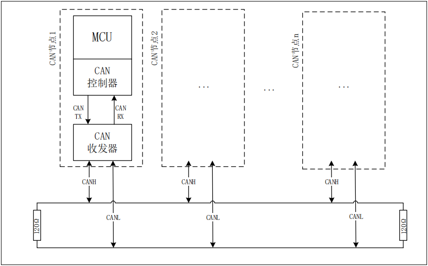
Figure 1 below: The CAN bus consists of two differential lines CANH and CANL, and each node is connected to the CAN bus through a shorter branch line. There is no master-slave or address distinction for each node in terms of the communication protocol, and each node can send and receive data equally. In addition, there is a 120 Ω termination resistor at each end of the CAN bus to do impedance matching to reduce echo reflection.
Figure 1 CAN network topology
CAN bus physical layer characteristics
Figure 2 below: Explicit level corresponds to logic “0”, and the voltage difference between CANH and CANL is about 2.5V. The implicit level corresponds to logic “1”, and the voltage difference between CANH and CANL is 0V. On the bus, the explicit level has priority, and as long as one node outputs the explicit level, the bus is at the explicit level. The invisible level has the meaning of inclusion, only if all nodes output the invisible level, the bus will be the invisible level.
Figure 2 CAN bus level characteristics

Frame Types
As shown in Table 1 below, the CAN contains the following five frame types. Data frames and remote frames are sent and received by the user; error frames, overload frames and interval frames are sent by the hardware of each node on the CAN bus according to the corresponding status and cannot and do not need to be controlled by the user.
Table 1 CAN frame types
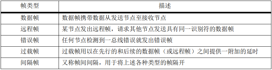
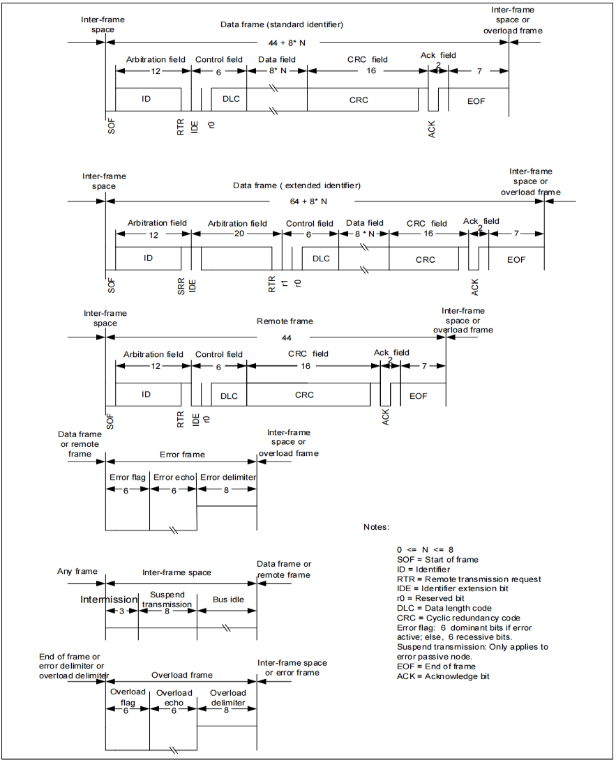
Figure 3 below contains a schematic representation of the frame structure for each type.
Figure 3 CAN frame types
Frame structure
This article only introduces the standard data frame in detail, other frame types can be compared with the standard data frame by referring to Figure 3 for understanding.
A standard data frame contains the following parts.
Start of frame: 1bit explicit bit. Since the CAN bus is at an implicit level when it is idle, the explicit bit at the beginning of the frame is used to indicate to the nodes on the bus that “a frame of information transmission has started”.
Arbitration segment: segment indicating the priority of the frame, containing the identifier and the frame type (data/remote frame).
Control segment: segment indicating the number of bytes of data, the type of identifier (standard/extended identifier) and the reserved bits.
Data segment: data, 0 to 8 bytes of data can be sent in one frame (data length is determined according to DLC of the control segment).
CRC segment: the sending node performs CRC calculation on the CRC calculation area (without padding bits) and sends it in the CRC segment. The receiving node also performs CRC calculation on the CRC calculation area and compares it with the received CRC field. If the CRC comparison result is wrong, it sends an error frame to the bus, and if the comparison result is correct, it subsequently sends an answer.
ACK segment: contains the answer bit (ACK SLOT) and the answer interval character (ACK DELIMITER). The transmitting node sends an implicit level in the ACK segment; the receiving node outputs a 1-bit explicit level in the answer bit to inform the transmitting node that “the frame was received correctly” if no error is detected during the reception.
End of frame: The segment indicating the end of the data frame is at 7 bit implicit level.
Figure 4 CAN standard data frame

Bit Fill
Since the CAN bus has only two differential lines, CANH/CANL, and no CLK line for synchronization, the CAN is synchronized directly by the jump edge in the middle of the data stream (see synchronization mechanism below). In order to avoid large sections of the data stream without a jump edge, CAN adds a “bit fill” mechanism.
That is, whenever the transmitter detects 5 consecutive bits of the same value in the bit stream, it automatically inserts a fill bit of the opposite level into the bit stream. For example, the original data stream is “0000000111110001…” and the actual output data stream to the CAN bus is “00000001001111100001…” after bit padding. “, the underlined bits are the fill bits.
The range of the bit padding is from Start of Frame (SOF) to CRC field (without CRC spacer), refer to Figure 4 above.
Bit Format
A bit of the AT32 CAN can be divided into 3 segments.
Synchronization Segment (SYNC_SEG)
Bit Segment 1 (BIT SEGMENT 1), including PROP_SEG and PHASE_SEG1 in the CAN standard, is noted as BSEG1.
Bit Segment 2 (BIT SEGMENT 2), which is PHASE_SEG2 in the CAN standard, is denoted BSEG2.
These segments in turn consist of the smallest time units of Time Quantum (hereafter referred to as Tq).
One bit is divided into three segments, each segment is composed of several Tq, which is called bit timing.
You can set the positioning timing arbitrarily by how many Tqs a bit consists of, how many Tqs each segment consists of, etc. The user sets the positioning timing and Tq length to set the CAN baud rate and sampling points. The baud rate and sample point settings are described in detail later.
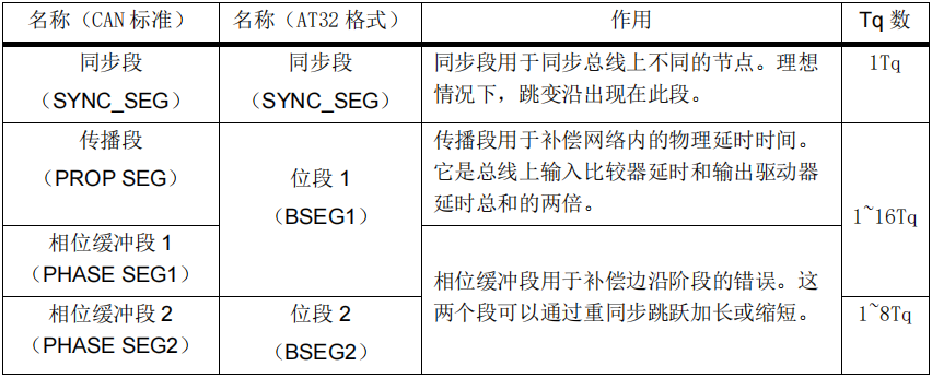
The role of each segment and the number of configurable Tq for the AT32’s CAN are shown in Table 2 below.
Table 2 Role of each segment of the bit
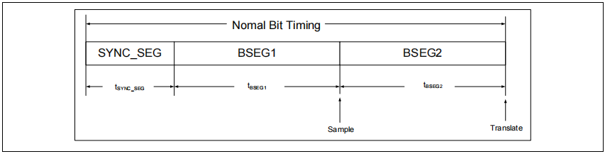
In Figure 5 below, the synchronization segment, bit segment 1 and bit segment 2 form a bit. The junction of BSEG1 and BSEG2 segments is the sampling point, i.e., the time point at which the receiving node samples.
Figure 5 Bit Timing
Synchronization Mechanism
HARD SYCHRONIZATION (HARD).
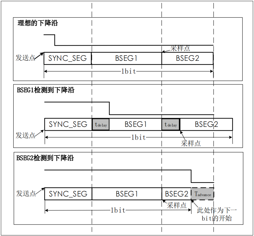
After hard synchronization, the internal bit time restarts from the synchronized segment. Therefore, hard synchronization forces the edge caused by hard synchronization to be within the restarted bit time synchronization segment. That is, the ideal jump edge case of Figure 6 below.
RESYCHRONIZATION JUMP WIDTH.
The result of resynchronization causes bit segment 1 to grow, or bit segment 2 to shorten. There is an upper limit to the number of bit segments that can be grown or shortened, and this limit is given by the RESYCHRONIZATION JUMP WIDTH. The resynchronization jump width should be set between 1 and 4 Tq.
Figure 6 below.
When a falling edge is detected in the BSEG1 segment, the BSEG1 segment grows Tdelay and the current bit grows Tdelay overall, where Tdelay <= resynchronization jump width.
When a falling edge is detected in BSEG2 segment, then BSEG2 segment shortens Tadvance, and the current bit shortens Tadvance as a whole, where Tadvance <= resynchronization jump width.
Figure 6 Resynchronization jump
Arbitration mechanism
Any unit can start transmitting messages as long as the bus is free. If 2 or more units start transmitting telegrams at the same time, then there is a bus access conflict. This conflict can be resolved by bit-by-bit arbitration of IDs. The mechanism of arbitration ensures that neither messages nor time are lost. When data frames with the same ID and remote frames are initialized at the same time, the data frames take precedence over the remote frames. During arbitration, each transmitting node compares the level of the transmit bit with the level of the bus being monitored. If the levels are the same, the node can continue sending. If a “recessive” level is sent and a “dominant” level is monitored (see Bus Level), then the node loses arbitration and must immediately exit the transmit state and move to the receive state.
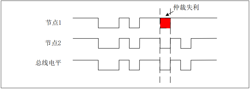
For example, in Figure 7 below, node 1 and node 2 send a frame of data at the same time, with the same first few bits of the ID segment. Until in red, node 1 sends an implicit level “1” and node 2 sends an explicit level “0”. At this point, node 2 wins the arbitration and continues to send, and the bus level is the same as the value sent by node 2; while node 1 loses the arbitration and goes to receive in the next bit, and the subsequent transmit pins of node 1 keep the implicit level.
Figure 7 Arbitration mechanism
Error handling mechanism
Error Types
The CAN protocol defines five different error types as follows.
Bit Error (Bit Error)
The unit monitors the bus while sending a bit. If the sent bit value does not match the monitored bit value, a bit error is detected during this bit time. The AT32 subdivides bit errors into explicit bit errors (explicit bit sent but implicit bit detected) and implicit bit errors (implicit bit sent but explicit bit detected). CAN nodes can have such errors in the transmit state.
The exception to this is when an “implicit” bit is sent during the ARBITRATION FIELD fill bit flow or during the ACK SLOT – when an “explicit” bit is monitored. When an “explicit” bit is monitored, no bit error is issued. When the transmitter sends a passive error flag but detects an “explicit” bit, it is also not considered a bit error.
Bit Stuff Error
A bit fill error is detected if six consecutive identical bit levels are detected in the bit fill area (refer to “Bit Fill Area” in Figure 4) using a frame of the message. This error occurs in the receive state of the CAN node.
CRC Error
The CRC sequence includes the result of the CRC calculation of the transmitter. The receiver calculates the CRC in the same way as the transmitter. If the result of the calculation does not match the result of the received CRC sequence, a CRC error is detected. Such errors occur in the CAN node in the receive state.
Format Error (Form Error)
A format error is detected when a fixed form bit field contains 1 or more illegal bits. For example, if a dominant bit is detected in the bit field of the CRC spacer/ACK spacer, a format error is detected. Exception: A dominant bit during the last bit at the end of the frame of the receiver is not treated as a frame error. Such errors occur in the CAN node in the receive state.
Acknowledgment Error (Acknowledgment Error)
The transmitter detects an acknowledgment error as long as the bit monitored during the ACK SLOT is not “dominant”. This error occurs in the transmit state of the CAN node.
Error Status
After the CAN node detects an error, the transmit error counter (TEC[7:0])/receive error counter (REC[7:0]) is incremented by 1 or 8 depending on the state and type of error (see the BOSCH CAN protocol for the increment rules), and the transmit/receive error counter is decremented by 1 for each correctly transmitted/received frame of data. Therefore the transmit/receive error counter value indicates the stability of the CAN node and network. Depending on the transmit/receive error counter value, a node will be in one of the following three states.
Error Active
An “error active” node can participate in bus communication normally and emits an active error flag (6 significant bits) when an error is detected. See Figure 8 below, TEC < 128 and REC < 128 is the error active state.
Error Passive
An “error passive” node can participate in the bus to receive and send data/remote frames. However, only the error passive flag (6 invisible bits) can be sent when an error is detected. See Figure 8 below, 255 ≥ TEC > 128 and 255 ≥ REC > 128 is the error passive state.
Offline
An “offline” node is equivalent to a direct disconnection from the CAN bus and cannot receive/send any information. See Figure 8 below, TEC>255 is the offline state.
AT32 offline management: The AT32 CAN recovers from the offline state in two cases.
1) When the CAN main control register (CAN_MCTRL) AEBOEN bit is ‘0’, software is required to request to enter the freeze mode and then request to exit the freeze mode, then wait for the CAN node RX to detect 11 consecutive implicit bits 128 times in the communication mode, and then the node will recover from the offline state.
2) When the AEBOEN bit is ‘1’, the CAN node RX in communication mode detects 11 consecutive implicit bits 128 times and then automatically resumes from the offline state.
Figure 8 Error State

CAN for AT32
The AT32 CAN supports the standard CAN protocols 2.0A and 2.0B. It is compatible with the standard CAN protocols and adds several features and configurable options. The main difference between CAN 2.0A and 2.0B is that CAN 2.0A supports only 11bit ID, i.e. only standard frames; CAN 2.0B supports 11bit/29bit ID, i.e. both standard and extended frames.
This chapter introduces the main design structure and use of AT32 CAN. It introduces the normal communication flow of AT32 CAN, including transmitting flow, receiving flow, message filtering, baud rate and sample point setting. For other AT32 CAN related designs, such as error management, interrupt management, etc., please refer to the RM related chapter.
Overall Function Introduction
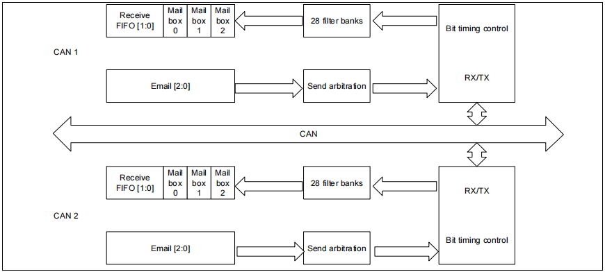
As the number of CAN network nodes and messages increases, an enhanced filtering mechanism is needed to handle various types of messages and reduce the processing time of received messages. The FIFO scheme is used to allow the CPU to process application layer tasks for a long time without losing messages. At the same time sending messages is controlled by hardware in order of sending priority. Based on the above considerations, the CAN controller provides 28 bit-width configurable identifier filter groups, 2 receive FIFOs, each of which can store 3 complete messages. There are 3 send mailboxes, and the send scheduler determines the send priority order. The whole sending and receiving process is completely managed by hardware and does not need to occupy CPU resources.
Figure 9 AT32 CAN overall function introduction
CAN Transmit Flow
The CAN transmitting process is shown in Figure 10 below and the following steps.
Users only need to operate 1) ~ 3) when using it. 4) ~ 7) are done automatically by hardware without user code involvement and do not occupy CPU resources.
1) The program selects 1 vacant mailbox (send mailbox empty flag TMxEF=1)
2) Write the message to be sent to the corresponding empty mailbox. The content of the message contains: ID, frame type, data length and data to be sent, etc.
3) Request to send: TMSR position 1 of CAN_TMIx
4) Mailbox pending (waiting to become the highest priority)
5) Scheduled send (wait for bus idle)
6) Send
7) Mailbox vacant
Note: The above steps 1) ~ 7) only briefly introduce the normal sending process. The following Figure 10 also contains the cases of canceling sending, sending failure, automatic/non-automatic retransmission, etc., which can be referred to the section on RM file message sending and will not be detailed here.
The flag bits and operation bits in Figure 10 below are described as follows.
TMxTCF: Request completion flag bit (send/abort request)
TMxTSF: send success flag bit
TMxEF: send mailbox empty flag bit
TMSR: request to send
TMxCT: Abort sending
PRSFEN: Prohibit automatic retransmission (when PRSFEN=1, automatic retransmission is prohibited; when PRSFEN=0, automatic retransmission until transmission is successful)
Figure 10 CAN transmission flow

CAN Receive Flow
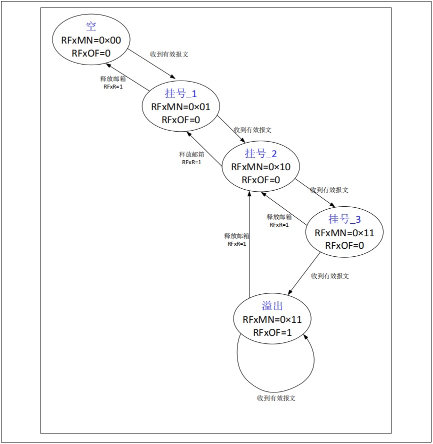
The common CAN receive flow is as follows, i.e. the cycle between the two states “empty” and “pending_1” in Figure 11 below.
1) FIFO empty
2) Receive a valid message
(3) enter the “registered_1” state (the state of a valid message in the FIFO)
4) Read the valid message: read the receive mailbox register (CAN_RFIx, CAN_RFCx, CAN_RFDTLx, CAN_RFDTHx).
CAN_RFDTHx).
5) Release mailbox: CAN_RFx register RFxR position 1.
Note: The user only needs to operate 4) ~ 5) when using. 1) ~ 3) are done automatically by the hardware, without the involvement of user code, and do not occupy CPU resources.
Valid telegrams.
A message is considered valid when it is received correctly (no errors until the last bit of the EOF field) and it passes the identifier filter. The filters are described in the next section.
And if the user does not participate in the operation during reception (i.e., does not bother to read the valid message and release the mailbox), the hardware flow is as follows.
1) Receive a valid message
2) Enter the “pending_1” state (the state of one valid message in FIFO)
3)Receive a valid message
4)Entering the “Registered_2” state (the state of 2 valid messages in the FIFO)
5)Receive a valid message
6)Entering the state of “Registered_3” (the state of 3 valid messages in the FIFO)
7)Receive a valid message
8) enter the “overflow” state (there are three valid messages in the FIFO, one message is lost, the overflow flag is set)
The following figure 11 in the flag bits and operation bits are explained as follows.
RFxMN: the number of valid messages in the FIFO (take the value of 0 ~ 3)
RFxOF: overflow flag bit
RFxR: Release mailbox
Figure 11 CAN receive flow
Filters
In the CAN protocol, the ID of a message does not represent the address of a node, but is related to the content of the message. Therefore, the sender sends the message to all receivers in the form of a broadcast. When the node receives a message, the value of the ID determines whether the message is needed by the software; if so, it is stored in the receive FIFO and the user can read the receive mailbox register to get the message; if not, the message is discarded without software intervention.
To meet this requirement, the AT32 CAN controller provides 28 hardware filter groups for the application (28 filter groups for the AT32F435 series, 027; but only 14 filter groups for the AT32F403A and other series, 013. Please refer to the RM of the corresponding model for details) in order to receive only those messages that are required by the software. After the user configures the required IDs, the whole filtering process does not require software participation and does not occupy CPU resources.
Bit width of filters
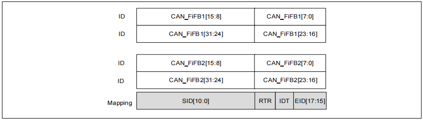
Each filter group consists of 2 32bit registers, CAN_FiFB1 and CAN_FiFB2. By configuring the FBWSELx bits of the CAN_FBWCFG register, two 16-bit wide or one 32-bit wide filters can be set.
The 32-bit wide filter register CAN_FiFBx includes: a set of SID [10:0], EID [17:0], IDT and RTR bits.
The 16-bit wide filter register CAN_FiFBx includes: two sets of SID[10:0], IDT, RTR and EID[17:15] bits.
Filter Mode
By setting the FMSELx bits of the CAN_FMCFG register you can set the filter register to operate in either the Identifier Mask mode or the Identifier List mode. The Mask mode is used to specify which bits of the ID need to be the same as the preset ID and which bits do not need to be compared, and the List mode indicates that each bit of the ID must match the preset ID.
Both modes are used in conjunction with the filter bit width to allow for the following four types of filtering.
Figure 12 32-bit wide identifier mask mode
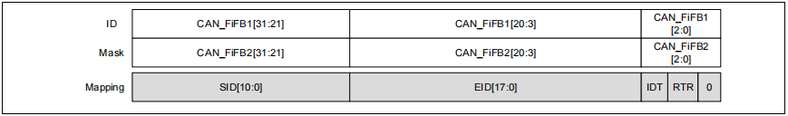
Figure 13 32-bit wide identifier list mode
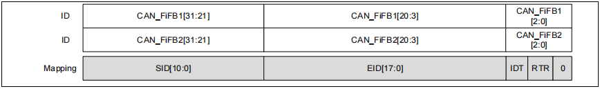
Figure 14 16-bit wide identifier mask mode
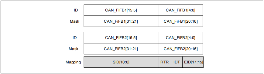
Figure 15 16-bit wide identifier list mode
More CAN filter descriptions, such as CAN filter matching number, priority rules, etc. can be found in the RM file message filtering section, and will not be detailed here. The filter configuration process is described in the case study – CAN Receive Filter Usage.