This application note discusses techniques for simultaneously changing the digital intensity of all LEDs on a display (panel intensity control) driven by the MAX6952 or MAX6953 5×7 LED matrix driver. This control is in addition to the bit-by-bit adjustment already provided by the driver. The note includes a calculator in the form of an Excel spreadsheet that can be downloaded to aid in the design.

This application note discusses techniques for adding panel LED intensity control to the 4-wire and 2-wire serial interface LED display drivers of the MAX6952 and MAX6953. Each LED driver controls four single-color or two two-color 5 x 7 matrix LED digits. Multiple drivers can be used together to form a message display.
These display drivers already have 16 steps of individual digital current control. The additional controls discussed here add a master intensity control that can reduce all individual digital currents at once in 4, 8 or 16 steps. This can be used, for example, to adjust ambient lighting conditions.
A single external resistor, R Aisett, controls the peak segment current for all segments. r Aisett absorbs the current from the driver’s internal reference voltage source and mirrors that small current internally to set peak segment currents of up to 40mA. Peak segment currents can be dynamically controlled by adjusting the effective value of R. Adjusting R Aisette adjusts the peak segment current for all drivers at once and therefore operates as a global intensity control. Panel intensity control can be built by adjusting R. At the same time, for all drivers in the display panel, has the same value.
Global intensity control of the Aisette with digital resistors, such as the 32-step MAX5160, can be achieved by replacing a fixed R. If fewer steps are required and alternate GPIO ports are available, these alternate ports can be used to directly control full-scale segment currents. These ports drive discrete resistors to build a simple R-2R-4R type DAC Aisette pin directly on R. The design software is an Excel spreadsheet for calculating resistance values for 2-bit DACs (resistors RA and RB), 3-bit DACs (resistors RA, RB, and RC), and 4-bit DACs (resistors RA, RB, RC, and RD). These DACs provide 4, 8, and 16 steps of intensity control, respectively (Figure 1). A separate resistor DAC is required for each driver in the panel; multiple ISET pins can be driven by a single DAC. However, multiple DACs (and therefore multiple drivers) can be controlled by a set of GPIO ports because the current absorbed into the ports by each resistor is small.
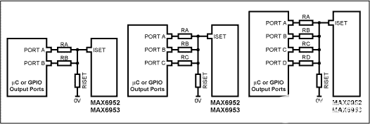
Figure 1. Add 2, 3, or 4 additional resistors to the external GPIO port to build a global intensity control DAC.
The DAC port should toggle between a logic low output with a DAC code of 0 and a high impedance (DAC code of 1). The open drain port output automatically implements this logic. A standard microcontroller GPIO port with a push-pull output can be set to a high impedance condition by switching the configuration of the port to logic input mode.
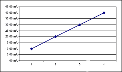
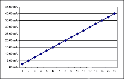
Figure 2.2 Screenshot of a bit Excel spreadsheet.
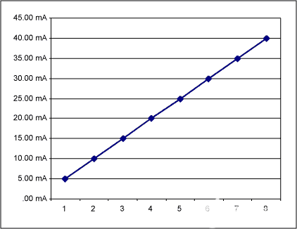
Figure 3.3 Screenshot of a bit Excel spreadsheet.