It’s a stunning, easy-to-make hat with a programmable LED display that can show any color, image and animation that you can put in an 8×8 matrix.

Background
If you’re tired of buying a different hat for every occasion, if you constantly switch between your favorite sports teams, or if you want a flashy, versatile and unique hat that no one else has, then we’ll show you how to make a relatively simple, customizable hat that can display any combination of colors, images and animations that you can put into an 8×8 LED display.
Create Screen
Step 1: Display the template
You will need to make a template for the LED matrix to determine the size of the area to be cut from the screen material and the cap. The template should be about 1/4″ wide on each side of the square to allow enough room for the bezel and hat attachments.

Step 2: Cut out the screen
You can make a protective screen cap for the display that will protect the LED matrix and help hide the LED matrix circuit board. The screen will be applied to the outside of the cap. Place a paper template in the center of the full face shield visor and trace the border with a marker. The outline of this visor matches the outline of the hat perfectly. Cut out the traced area with a sharp pair of scissors.

Step 3: Cut the border material
The screen wouldn’t look very good if applied directly to the hat, so we borrowed some material from the inside flap of the hat to create a border around the screen. A very sharp pair of fabric scissors was used to cut this material. We didn’t have scissors, so we used a pair of tin snips. Make sure to leave a few inches of flap on the cap. We will use this flap later to tuck in the electronics. With this particular hat, we started cutting from the end about an inch from the tab.

Step 4: Drill sieve holes
You will need to sew the freshly cut material to the edges of the screen. But since it’s hard to get a needle through the plastic, take a small drill bit and drill holes about 5 to 8 mm along all four edges.

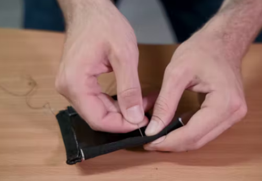
Step 5: Stitching the border
Next, cut the bezel material into 4 strips, each measuring the length of one side of the screen. Then, take a sewing needle and thread and sew the material around the border using the pre-drilled holes. We used a continuous stitch pattern. It’s okay if there is some overlap in the corners; it will look great on the hat.
This is the screen. Next, after preparing the hat, we will attach it to the front of the hat using the fabric trim we just put on.
Modify hat
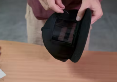
Step 6: Trace the display hole
Since the LED matrix and electronics will be mounted inside the hat, we need to cut out a hole from the hat for the display. Take the same paper template made earlier and very carefully place it in the center of the inside of the hat. Trace the template with the manufacturer and cut out the area. We found that the box cutter with the sawing motion worked well and cut fairly cleanly. Don’t worry if the edges are not very clean; they will be covered by the border of the screen.

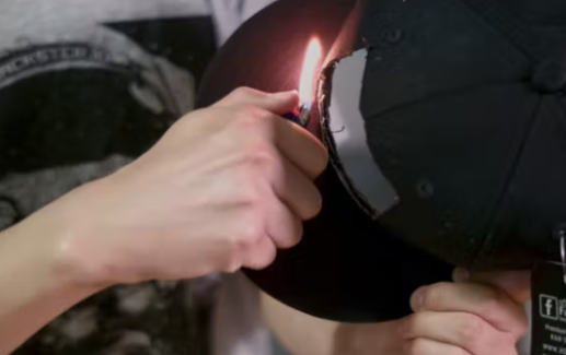
Step 7: Clean up the edges (optional)
If you want to clean up the edges a little, you can take a lighter and burn off any loose threads that are hanging off the edges.
Step 8: Sewing screen on the hat
We can now attach the screen to the hat. Simply sew the screen to the hat using the fabric hem (you don’t have to pierce the plastic material). We use the same continuous stitch sewing pattern.
Installation Hardware
Step 9: Attach the LED matrix to the hat
Now the hat is finally ready for the LED matrix. Fortunately, there is no more sewing involved. Carefully place the 8×8 RGB flexible LED matrix behind the square hole with the wires facing the flap of material you left behind to hold the electronics. Then take some Gorilla Tape and attach it to the bezel of the LED matrix.

You will also need to remove the top two sets of wires from the back of the LED matrix before attaching them to the cap. You can do this by heating the contacts where the wires are attached with a soldering iron. The picture above shows the silver electrical contacts used to connect the wires.
Step 10: Cover all electrical contacts
To prevent anything from inadvertently shorting out the electrical connections on the back of the LED matrix, take three small strips of electrical tape and cover all contacts.

Step 11: Connect the wearable electronic platform
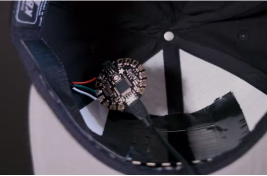
The display is controlled by a small Flora wearable electronic platform from Adafruit. You will need to solder some extension cords to the leads coming out of the display so that you can connect the electronic platform. In step 3, use enough wire to extend to the inside of the flap on the left side of the hat.
Next, solder the other end to the contacts on the platform shown below: the white wire is grounded, the green wire is connected to #6, and the red wire is connected to VBATT.

Step 12: Install the electronic platform and battery
Use tape to tie up the wires along the inside of the cap towards the flap. Connect the Adafruit 3.7V 500mAh lithium-ion polymer battery to the electronics platform. Then tuck both the battery and the electronics platform into the flap. We found that the components stayed in place nicely without any help.

Software
Step 13: Programming and loading the software
To program the display, plug the Flora electronics platform into your computer using a USB cable. The platform can be programmed using the Arduino IDE.
Step 14: Put it on
Now go show off!