As we all know, FBAR filter is a thin film cavity acoustic resonance filter, it is different from the previous filters, it is manufactured by using silicon substrate, with the help of MEMS technology and thin film technology, the current stage of FBAR filter has slightly higher than the characteristics of ordinary SAW filter. Today we will take a look at the theory of FBAR filters and discuss the design of FBAR filters.
By reviewing the information we learned that the physical basis of FBAR filter comes from the discovery of the Curie couple, to be exact, Madame Curie’s husband and his brothers: Pierre Curie and Jacques Curie. The Curie brothers discovered in 1880 the magic piezoelectric effect: a physical phenomenon of correlated conversion between mechanical forces and electricity. Later scientists used this piezoelectric effect to create acoustic resonators: surface acoustic resonators and body acoustic resonators

The thickness of the piezoelectric film and the speed of sound determine the resonant frequency of the resonator, f0. Its working process: When the AC voltage is applied to the upper and lower electrodes of the FBAR, the piezoelectric film will deform due to the inverse piezoelectric effect, will produce deformation; and the deformation of the piezoelectric film will produce a piezoelectric effect, will make the charge polarity inside the piezoelectric film is no longer symmetrical, resulting in polarization. When the frequency of the input AC voltage signal is equal to the mechanical change frequency of the piezoelectric film, a mechanical wave standing wave will be formed on the surface of the electrode, thus forming mechanical wave resonance, which is also known as acoustic resonance.
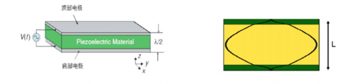
So, it is by using this amazing piezoelectric effect of the piezoelectric film that FBAR accomplishes the conversion of electrical and mechanical energy. The resonant frequency can be determined by the following equation.

f0 is the resonant frequency of the FBAR, v is the body acoustic wave speed within the piezoelectric material, and L is the equivalent body acoustic wave thickness determined by the piezoelectric film and the two electrodes together. Similar to the microwave resonator, the impedance characteristics and phase characteristics of the FBAR are shown below. From the impedance characteristics curve, it can be seen that the FBAR has two resonant frequencies, the lower frequency is the series resonant frequency fs, the resonant point has the lowest acoustic impedance, and the signal can pass completely; the higher frequency is the parallel resonant frequency fp, the resonant point has the highest acoustic impedance, and the signal cannot pass. Observing the phase characteristic curve, it can be found that the phase between the two resonant frequencies is +90°, showing inductive; while the phase outside the two resonant frequencies is -90°, showing capacitive. In other words, for the FBAR operating at non-resonant frequencies, it is equivalent to the flat capacitor characteristic.
.

According to the impedance characteristic distribution of FBAR, a bandpass filter with excellent performance can be obtained by cascading the parallel resonant frequency and series resonant frequency of multiple FBARs according to certain laws. Then how to constitute an FBAR? In the previous article, we introduced the three most common FBAR structures: back-side etched type, cavity type and solid-state reflective type, in which both etched type and cavity type are made by carving air slots on the electrode side of the FBAR to achieve the total reflection of the acoustic wave at the interface between the electrode and the air, thus forming a standing wave. The solid-state emitter type achieves total reflection of the acoustic wave by loading a bragg reflector on one side of the electrode. From the performance point of view, the air-reflecting type is more effective and has less leakage, but the structural strength is slightly lower, while the Bragg-reflecting type has more structural strength, but the acoustic leakage will be relatively large and the loss of the formed filter is also larger.

The principle is quite simple, and the structure is not complicated, so how exactly to “dry” it?
A more accurate method is to use multi-physics field simulation, by building a multi-physics field model of FBAR and bringing it into the simulation software for FEM simulation, so as to obtain the piezoelectric coupling performance of FBAR.

Another relatively fast method is to quickly simulate the acoustoelectric properties of FBAR by building an equivalent circuit model of FBAR. A simpler equivalent circuit model is the modified Butterworth Van Dyke model (mBVD), which uses simple inductors, capacitors and resistors to simulate the electro-acoustic properties of the FBAR; the other is the Mosen model, which can simulate the parasitic modes and high submodularity of the FBAR and is more accurate than the mBVD model.

These two methods are relatively fast in computational iterations and are often used in filter optimization iterations. Today, we will focus on the Mosen model to learn more about the working mechanism of FBAR by corresponding the mechanical analysis to the electrical model.
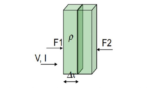
Let us first look at the departure of the intrinsic equation of the piezoelectric material.

A time derivative for its trace deformation yields

According to the relationship between voltage and electric field, bringing in the above equation can get

It can be seen that the acoustic pressure F and voltage V are determined by the acoustic current v and current I together, i.e., the acoustoelectric coupling. We separate the relationship between the acoustic pressure F and acoustic current v in the above equation and use a capacitor C to obtain the equivalent circuit model of the piezoelectric characteristic microcell model, as shown in the following figure.
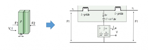
Combining the equivalent inductance L in the above figure, further optimized into a transmission line mechanics model, we can obtain

A simplification of the voltage V in the above equation yields
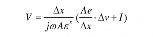
From the above equation, it can be seen that part of the voltage V of the piezoelectric material can be considered as the voltage across the equivalent capacitance C0 = Aes /x, and the other part is contributed by the acoustic current v coupled to the electrical port by mechanical vibrations. The physical sources of these two currents are not the same, so an ideal transformer is used to isolate the acoustic and electrical branches from each other, and the ratio of the ideal transformer is also used to match the magnitude of the current from the acoustic current to the electrical side, with a current ratio of -Ae/x , with a negative sign indicating the opposite direction to the electrical port current. In turn, a complete Mosen model of the piezoelectric material can be obtained.

This allows us to further obtain the electrical impedance equation for piezoelectric materials
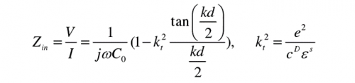
Kt2 is the electromechanical coupling coefficient of the material, which characterizes the electromechanical conversion capability of the piezoelectric material and can be solved using two known resonance points.

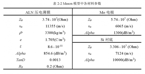
The magnitude of the electromechanical coupling coefficient embodied in the piezoelectric material directly determines the frequency spacing between the series and parallel resonant frequencies of the FBAR resonator, and then indirectly affects the relative bandwidth of the FBAR filter that can be achieved. Based on the Mosen model established above, it can be modeled and simulated in the ADS simulation software, as shown in the following figure, with the following table of material parameters in the model. The piezoelectric material area size A and the piezoelectric material thickness correspond to the transmission line length D in the figure and are used to correspond to specific different resonator structure parameters. It is worth mentioning that in this Mason model, the variable Alpha in the three-port transmission line is used to define the mechanical loss in the model, TanD to define the dielectric loss, and the ohmic loss is characterized by using a series resistance in the electrical port, which can be obtained in the subsequent parameter fitting process to obtain the optimal value of this resistance

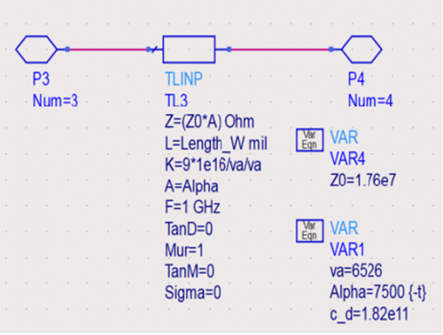
For non-piezoelectric materials such as electrodes, substrates, and support layers, the acoustic properties are usually modeled by a simple transmission line model, as shown below, where the material’s intrinsic parameters can be directly defined by Z0 and the longitudinal sound velocity va, or calculated from the density and stiffness coefficients c parameters.
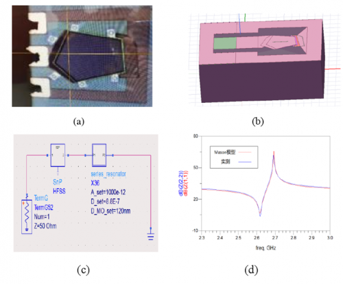
Finally, the acoustoelectric ports of each part are cascaded to obtain the equivalent Mason model of the FBAR resonator as shown below. Since the resonant frequency of FBAR is generally changed by the thickness of the upper electrode and the piezoelectric film, the thickness of the lower electrode and the substrate are fixed according to the specific process conditions. Neglecting the thinner support layer, the upper and lower electrodes and substrate of the FBAR resonator are in contact with air, and no external force is applied, so the acoustic port after cascading is grounded on both sides, and the substrate module can also be considered to be removed during the implementation of the model.

The Mason model of the resonator is used as the basis of the FBAR filter design, and the accuracy of the model parameters directly determines the accuracy of the subsequent FBAR filter design. The parameters of the Mason model are extracted and modified using the results of multi-physics FEM simulations or the results of de-embedding to obtain the parameter fit, or more detailed simulations can be performed using HFSS and other electromagnetic simulation software to obtain more accurate FBAR parameters.
Like conventional microwave filters, the filter effect can be realized by arranging several FBARs in a certain order of combination to form a filter.
What does a filter composed of FBARs look like?
The two most common FBAR filter topologies are lattice and ladder, as shown in the figure below, where the individual FBAR resonators are not coupled to each other and work as independent resonator units. The lattice connection structure in figure a below are both double-ended and double-ended output structures, which feature wider bandwidth and good far-end rejection, but have the disadvantage of poor rectangular coefficients, limiting the application of this structure.
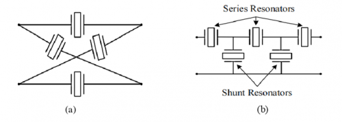
Figure b shows the ladder structure, usually grounding the parallel resonator to achieve a single-ended input-output structure, which is more widely used. The structure of the ladder connection topology is mainly composed of series and parallel resonators, and the series resonator resonant frequency is always higher than the parallel resonator. The working principle of FBAR filter based on ladder connection is shown below. When the frequency of the signal is the series frequency of the parallel resonator (fs SH), at this time the parallel resonator presents the smallest impedance, while the series resonator impedance is larger, so most of the signal passes through the parallel resonator to the ground to form the transmission zero at low frequencies. When the signal frequency is the parallel resonant frequency of the series resonator (fp SE), at this time the series resonator presents the largest impedance, while the parallel resonator is smaller, so most of the signal will also pass through the parallel resonator to the ground to form the transmission of high frequency at the transmission zero point. Only when the signal frequency is near the parallel resonant frequency (fpSH) of the parallel resonator and the series resonant frequency (fs SE) of the series resonator, the signal can ideally pass through the two-port filter network without loss.

So in terms of filter implementation, it is also much simpler than ordinary microwave filters, without having to consider the complex coupling and parasitic coupling inside the resonator, to achieve higher rejection, simply by adjusting the number of series and parallel FBAR resonators, but its out-of-band performance is also not as smooth as ordinary microwave filters to. Its higher single FBAR quality factor enables steeper rejection, but the insertion loss calculation is not fully equivalent to that of a normal microwave filter.