This article is selected from Physics, Vol. 12, 2022
Abstract Phantom optics based on transformation optics are able to exhibit phenomena that do not exist in nature, such as stealth, superscattering, and invisible doors. Among these phenomena, electromagnetic superscattering uses the folding geometric transformation in transformation optics to make the scattering cross-section of an object much larger than its geometric cross-section, overturning the perception that the scattering cross-section in conventional scattering is usually smaller than the geometric cross-section of the scattering body. This phenomenon also provides the possibility of “wall penetration” in reality. The article focuses on the development of superscattering based on transformation optics and the method of using superscattering to realize invisible doors. The implementation of invisible doors in free space provides new ideas for the design of future phantom devices.
1 Introduction
Many films and literary works have a fascinating portrayal of “invisibility”, the most famous of which is the invisibility cloak in Harry Potter, where the cloak is invisible to the outside world. The key to invisibility is the manipulation of light, as people can perceive objects because they receive light reflected from them. In mythology, wall-piercing refers to the superpower of a person as a subject to pass through a solid wall, while in reality, “wall-piercing” is achieved by changing the special optical properties of the wall. For electromagnetic waves, wall penetration is the ability of an object to pass through a special door that is not visible to the observer, i.e., an “invisible door”. Wall penetration with invisible doors is closely related to illusion optics. One typical example is the hyperscattering effect, in which the scattering cross section of a scattering body is extremely increased [1], i.e., the size of the object becomes large for the observer. Theoretical studies have shown that superscatterers can be realized by using a compensating medium [2] combined with a transformation optics approach [3]. This approach has been used to design many wonderful and interesting phantom optics devices, such as invisible channels or invisible gates based on the superscattering effect [4], superabsorbers [5], non-wrapped cloaks [6] and endoscopes [7], among which invisible gates are the most popular phantom optics devices. The invisible door was first theoretically realized by researchers in 2009 through the rational design of the dielectric constant ε and the magnetic permeability μ (or refractive index n ) of the material. However, this invisible gate requires an extremely demanding refractive index distribution of the required material [4], which is difficult to implement experimentally. Later on, an invisible gate design scheme based on simplified parameters was proposed [8], and the existence of invisible gates was verified using circuit equivalence [9]. However, it was not until 2021 that a real invisible door was experimentally confirmed. In collaboration with Rui-Xin Wu’s group and Huan-Yang Chen at Nanjing University, the phenomenon of superscattering was verified for the first time in free space at microwave frequencies, and the phantom optical device, an electromagnetic invisible gate, was realized experimentally [10].

It took more than ten years from the first theoretical proposal to the final experimental realization of the invisible gate. In this paper, we will focus on the development of invisible doors, which is outlined in three aspects: firstly, the formulation of the powerful theory of transformation optics; secondly, the proposal from the quasi-static limit to electromagnetic superscattering; and finally, the theoretical design of invisible doors based on the superscattering effect and the experimental verification. The successful experimental implementation of the invisible gate will provide new ideas for the future application and development of new optical field modulation devices.
2 Transformation optics
Light propagates in a homogeneous medium in a straight line and is deflected when it passes through the intersection of two media. In life, chopsticks placed in a transparent cup with water seem to be “broken” as a reflection of this principle. The miraculous mirage phenomenon occurs when the refractive index has a gradual distribution, for example, when the density of the air on the desert varies due to the uneven temperature. This makes us think that if a medium with a certain refractive index distribution is designed, then light will propagate in it in a specific direction.
In 2006, Pendry et al [3] and Leonhardt [11] independently proposed a method to design a stealth cloak by transforming optics, respectively. As shown in Figure 1(a), in a “virtual space”, i.e., a vacuum, light propagates along a straight line, and through coordinate transformation, a point in space expands to form a circle in a “physical space” (Figure 1(b)), and light propagates around a red circle. Therefore, the inside of the red circle is invisible to the outside, giving the effect of invisibility [12]. This theory was proposed to make the magical invisibility cloak in Harry Potter possible to be realized. Subsequently, Smith et al. experimentally realized a single-frequency two-dimensional stealth device at microwave wavelengths using open-ended resonant rings as structural units of superconformal materials [13]. Since then, transformation optics has attracted a lot of attention due to its ability to freely manipulate the optical field.

Fig. 1 Coordinate transformation (a) light propagating along a straight line in free space before transformation; (b) a point expanded into a circle (red circle) by transformation and light propagating around the circular region [12]
The core of transformation optics is the establishment of transformation relations in two spaces (virtual and physical space) by coordinate transformation. Since the set of Maxwell’s equations has formal invariance before and after the coordinate transformation, the electromagnetic parameters (permittivity ε and permeability μ) in both spaces can be established in correspondence with the coordinate transformation [14].

Among them

is the Jacobi transformation matrix of virtual space and physical space, i, j, and i ‘, j ‘ are chosen from 1 to 3 to represent the three spatial coordinates, respectively. Many devices with novel functions can be designed using transformation optics, such as stealth cloaks [15], rotating cloaks [16, 17], convergers [18], and phantom devices.

Fig. 2 Some phantom optical devices and their corresponding coordinate transformation relations (a) ideal stealth cloak; (b) stealth cloak after weakening design; (c) stealth cloak based on Fabry-Perot resonance; (d) stealth device after folding transformation; (e-h) transformation relations of corresponding devices corresponding to virtual space r and physical space r ′, where The yellow dots correspond to the transformed transformation points, and r and r ′ denote the radii of the concentric rings before and after the transformation, respectively
Since the introduction of transformation optics, the most attention has been paid to the design of “stealth cloak”, as shown in Figure 2(a), which can guide the light to propagate around the object, thus making the object “invisible”. In cylindrical polar coordinates, the transformation relation corresponding to this ideal two-dimensional cloak is shown in Fig. 2(e), namely.

However, such an ideal stealth cloak can only operate at a single frequency point and cannot achieve perfect stealth effect in a wider frequency range. To address this problem, Huan-Yang Chen et al. proposed the dispersive stealth cloak [19], which operates at a broadened frequency compared to the ideal stealth cloak, but is accompanied by a partial sacrifice of performance. The core idea of the dispersive stealth cloak design is to use a more general form of transformation, as shown in Fig. 2(f), to compress one eccentric circular region region r0 < r ≤ r2′ into another eccentric circular region r1′ < r ≤ r2′, and the transformation returns to the ideal stealth cloak case when r0 = 0. Such a stealth cloak is a weakly designed stealth cloak, as shown in Fig. 2(b), which is equivalent to the existence of a tiny scatterer of radius r0 in free space. Therefore the transition point of the coordinate transformation corresponding to Fig. 2(f), i.e., r1 in the virtual space, is elevated compared to Fig. 2(e).
In 2015, the group of Huan-Yang Chen/Hou Bo introduced Fabry-Perot resonance into the design of transformation optics devices [20], such that the devices can operate at multiple resonant frequencies, making the multi-frequency application of transformation optics devices possible. As shown in Figure 2(g), the core of the transformation is the mapping of r1 ≤ r < r2 in virtual space to a concentric cylindrical layer r1′ ≤ r < r2′ in physical space, and this transformation corresponds to a wave stealth converging device when r2′ = r2 and r1′ < r1. When r1 converges to r2, it corresponds to the extreme version of the stealth convergence device. Further, when r1′ ≤ r < r2′, let εr = ∞, εθ = εθ(r ′) and μz = 1 (the transverse magnetic mode corresponds to the magnetic field along the z-direction), where εr and εθ correspond to the permittivity components in the r-direction and θ-direction, and μz corresponds to the permeability component in the z-direction; and when 0 ≤ r ′ < r1′, let ε = (r2′/r1′)2 and μz = 1, then this device is a Fabry-Perot The Fabry-Perot resonance condition for the stealth convergence device with r-direction can be written as

When m = 3, r2′ = 2, and r1′ = 1, εθ(r′) = (3 – r ′)2, the electromagnetic wave distribution is shown in Fig. 2(c), and this device is experimentally verified.
When the position of the marker point chosen for the transformation is further elevated, it corresponds to the folded geometric transformation. Unlike the three previously mentioned transformations, the folding transformation shown in Fig. 2(h) will introduce negative refractive index materials (ε<0, μ<0) due to the negative slope [21, 22]. Negative refractive index materials do not exist in nature, but negative refractive index materials with both ε and μ negative can be constructed by artificial superconfiguration materials [23, 24]. In negative refractive index materials, light propagation is opposite to its propagation properties in conventional materials, which leads to many “counter-intuitive” optical phenomena and provides more possibilities to manipulate light propagation. One of the most famous applications is Pendry’s proposal to achieve perfect imaging beyond the diffraction limit [22]. This imaging process, in terms of geometrical optics, can be understood from the perspective of transformation optics as a collapsing transformation of space, from a single point in virtual space corresponding to three points in physical space [25]. Back in 2003, Pendry proposed the concept of a compensating medium based on a negative refractive index flat plate [2], which consists of two regions with opposite electromagnetic properties, where light does not accumulate in phase after passing through the compensating medium and looks as if this region does not exist [26]. In Fig. 2(d), the materials in three circles from inside to outside are, in order, the homogeneous medium (r < r1′), the negative refractive index material (r1′ < r < r2′) and air (r2′ < r < r3′), and the air and negative refractive index layers constitute the compensation medium, i.e., optical voids are formed between the regions (r1′ < r < r3′), and there is no accumulation of phase after light propagation. The scattering properties of this system depend mainly on the object placed in the core layer [26].
The combination of negative refractive index and compensating medium also allows the design of many interesting phantom optics. Lai Chyun et al. proposed a non-wrapped stealth [6], which is based on the principle of using a compensation medium to eliminate the reflection of the stealthy object to achieve the stealth effect. This is different from the cloaking device in Fig. 2(a), where the observer inside the cloaking device in Fig. 2(a) cannot see the external situation because the light cannot enter inside r = r1′ , while the observer inside the non-wrapped cloaking can see the external situation. Anti-stealth devices can also be designed by folding geometric transformation to destroy the stealth effect of stealth devices composed of positive refractive index materials [27]. These amazing phantom devices make one wonder if what is seen is real?
3 The proposal and development of electromagnetic superscattering
Electromagnetic waves are scattered when they are incident on the surface of an object, and electromagnetic scattering is a very common physical phenomenon [28]. For example, the blue color of a clear sky is due to Rayleigh scattering: the size of molecules in the air is much smaller than the wavelength of light, and the shorter wavelength of blue light in visible light makes it easier to scatter, which is the physical mystery of the blue sky. Mie scattering occurs when there are more dust particles and liquid droplets in the air that are larger than the wavelength of light, and in Mie scattering all wavelengths of light are equally scattered, so the sky is grayish white. Electromagnetic scattering also has many important applications. For example, in the field of communication, the scattering effect of the troposphere on electromagnetic waves can be used for over-the-horizon communication; in military radar detection, information about the scattered object can be obtained by analyzing the scattering characteristics.
It can be seen that in conventional scattering, the scattering characteristics are closely related to the scatterer size, and the scattering cross section of an object is usually smaller than its geometric cross section. Ordinary materials have limited ability to modulate electromagnetic waves, and the scattering cross section only converges to the geometric cross section even for scatterers with larger wavelength size compared to the wavelength. Some scattering cross sections obtained beyond the geometric cross section based on resonance effects can also be distinguished from non-resonant scatterers by analyzing the Mie scattering coefficients at various levels. The emergence of transformation optics and metamaterials has greatly enhanced the ability to manipulate the electromagnetic field, making the scattering characteristics of small objects indistinguishable from those of large objects, i.e., the “superscattering” phenomenon, in addition to perfectly eliminating the stealthy effect of scattering. This phenomenon reverses the traditional perception that the maximum scattering cross section of a large scale object is its geometric cross section in electrodynamics.
Superscattering makes an object appear larger than its actual size by enhancing the scattering cross section. This phenomenon has a wide range of applications in sensing [29], converging energy [30, 31], fluorescence imaging [32], and wireless transmission of electricity [33]. Considering the scattering problem from a nuclear layer structure as shown in Figure 3(a), in the quasi-static limit (i.e., the object size is much smaller than the wavelength), the problem can be solved using an approximate system of Maxwell’s equations and the response of an object consisting of a core layer (ε1), a shell layer (ε2), and a background material (ε3) to a source with a discrete electric dipole can be analyzed by neglecting the other terms and considering only the dipole term [34] [ 35]. When ε1 + ε2 = 0 and ε2 + ε3 = 0, the object has no effect on the external field; while only when ε2 + ε3 = 0, the scattering from the core layer exceeds that from the shell layer, as if the radius of the core layer is amplified. The phenomenon of the core layer being amplified can be produced in the quasi-static limit, and the transition from the quasi-static limit to electromagnetic scattering (scattering from other order terms needs to be considered). There are three main approaches to achieve superscattering: the first one is to achieve superscattering by transforming the optics and introducing the concept of a compensating medium to amplify the object [1]; the second one is to achieve the superscattering phenomenon by breaking the single-channel scattering limit using the resonance of equipartition excitations on the surface of multilayer metal-dielectric subwavelength nanopillars [36, 37], which is achieved by resonance can only achieve a limited order of amplification, and the loss of materials has a significant impact on the scattering enhancement effect; the third one is to use near-zero refractive index materials to enhance object scattering [38, 39], which requires a near-zero refractive index background environment and poses further challenges for preparation and compatibility. This paper focuses on the first approach to achieve superscattering, which is further described below.
Under quasi-static conditions, the low-order scattering coefficient plays a decisive role, and when the size of the object is comparable to the wavelength, the higher-order scattering cannot be neglected, and the superscattering of objects with sizes comparable to the wavelength can be achieved by means of transformation optics [1]. Starting from the negative refractive index flat plate in Fig. 3(b), a point source S is placed at a position smaller than the thickness of the negative refractive index flat plate (yellow area), and it is known by geometric optics that the point source S will be imaged at F2 and F1. With a perfect electric conductor boundary (PEC) at R1, the light will be bounced back, while the region R2 < x < R1 and the region R3 < x < R2 form a pair of compensating media, and the perfect electric conductor boundary at R1 seems to be moved to R3. The plate is then rolled into a cylinder as shown in Fig. 3(c), and using the coordinate transformation of Fig. 2(h), similarly, region R1 < r < R2 and region R2 < r < R3 constitute a compensating medium, and the boundary of the perfect electric conductor at the interior r = R1 is visually shifted to r = R3, and the geometry of the object is equivalently enlarged to achieve the super-scattering effect. Figures 3(d) and 3(e) show the results of COMSOL simulation calculations, where the black solid line indicates the cylindrical boundary and the black dashed line indicates the equivalent region after scattering enhancement.
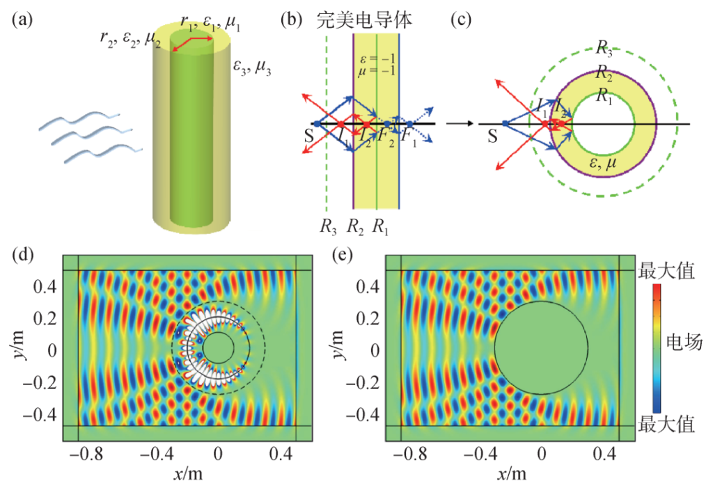
Fig. 3 (a) Schematic diagram of electromagnetic scattering from a nuclear layer structure; propagation of light in a flat negative refractive index material (b) and a cylindrical negative refractive index material (c), where the green solid line is a perfect electric conductor [1]; (d) total electric field distribution around a super-scattering cylinder with inner and outer radii R1 = 0.1 m and R2 = 0.2 m, respectively [1]; (e) total electric field of a perfect electric conductor with radius R3 = 0.3 m distribution, (d), (e) both for plane wave incidence [1]
The electric field distribution of Fig. 3(d), (e) is the same when a transverse electric mode (electric field along the z-direction) plane wave with a frequency of 3 GHz is incident, demonstrating the superscattering phenomenon. The physical mechanism behind it is the amplification of the negative refractive index shell layer for swift waves. This superscattering phenomenon has been shown to amplify not only cylindrical-shaped objects but also objects of other shapes [26, 40].
4 Implementation of an electromagnetic invisible door In the movie Harry Potter, the

The station is an invisible passage (or invisible door) to board the Hogwarts Express, as shown in Figure 4(a), which is both magic and can be an illusionary optical effect, i.e. this passage is physically present in space, but an observer outside the passage cannot see it from the visual level. With the continuous development of transformation optics, researchers have found that the invisible channel effect can be achieved when combined with superscattering techniques.
In 2009, Hongru Ma/Xudong Luo’s group [4] at Shanghai Jiao Tong University further developed the proposed superscatterer in Figure 3(d) by extending it to a square superscatterer and placing it between two appropriately distant metal walls. As shown in Fig. 4(b), where the height of the perfect electric conductor is 2b3 and the width of the area of the invisible channel is designed to be 2a3. when there is no superscatterer in the area of |x| ≤ a3+δ, then this channel area ( |x| ≤ a3+δ ) can obviously be detected by analyzing the scattered electromagnetic waves, and when a designed square superscatterer is placed in this channel area (which is the area surrounded by the Γ2 boundary surface), since the super The scattering cross section is larger than its geometric cross section, so the electromagnetic waves cannot pass through, thus creating an “invisible” channel. They used COMSOL simulations to show that when the incident light source is located on one side of the invisible door, the observer sees a very different “view” on each side of the invisible channel, as shown in Figure 4(d), (e). Although this invisible door design is consistent with the actual scenario, it requires negative refractive index materials to implement and requires a demanding refractive index distribution of the materials, which limits the development of invisible channel devices.
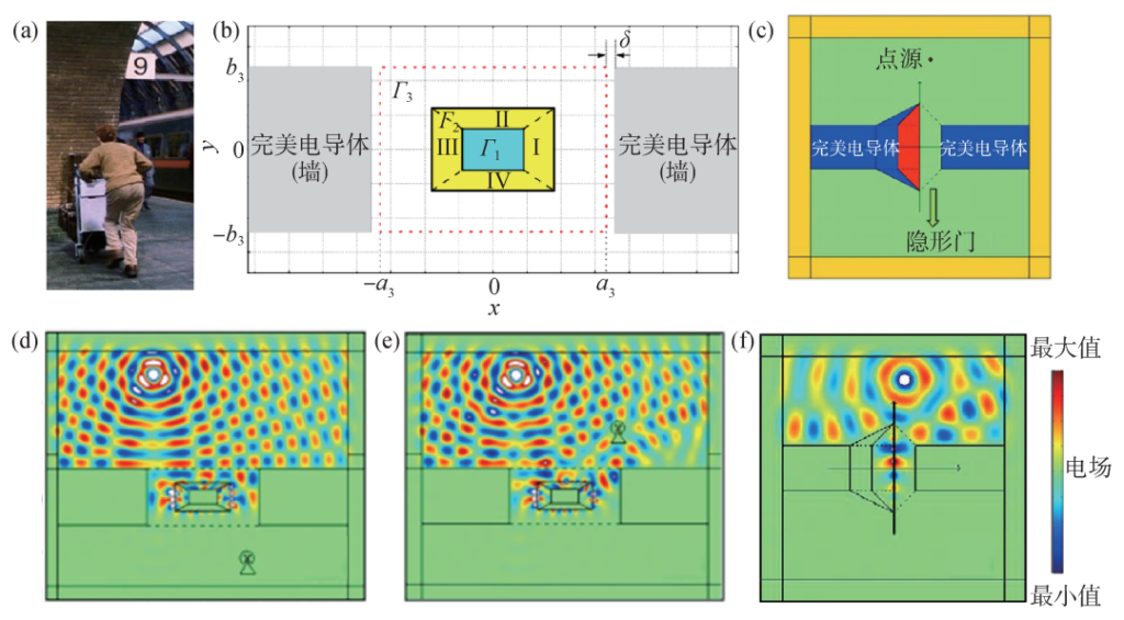
Fig. 4 Theoretical prototype design of the invisible door 4, 8 Harry Potter in

station; (b) a wrapped invisible door, where Γ1 is a perfect electric conductor region, Γ2 is a negative refractive index wrapped region, and Γ3 is a region through which electromagnetic waves cannot pass; (c) a simplified invisible door; (d), (e) corresponding to the invisible door in (b), and the effect of an observer located on each side is demonstrated by simulation; (f) corresponding to the invisible door effect in (c)
In the same year, Huan-Yang Chen et al [8] proposed a simplified invisible door prototype design, as shown in Figure 4(c). This new superscatterer no longer requires a material with a complex refractive index distribution, but instead is filled with a material with a partial refractive index of -1 and also has a certain operating bandwidth. Under the excitation of the light source, the presence of the negative refractive index material (red region in Fig. 4(c)) excites surface waves at the air-material interface, which in turn exhibit the phenomenon of superscattering, with a scattering cross section equivalent to the mirror image of the additional filled negative refractive index material region of the device itself. In the case of considering the transverse electric mode, the invisible channel is naturally formed by placing perfect electric conductors at both ends of the superscatterer. As shown in Figure COMSOL simulation result 4(f), the electromagnetic wave on one side is perfectly “blocked” when passing through the air channel of the device, but allows the object to pass through, acting as a perfect invisible gate. In addition, they also presented a scheme to implement invisible doors using magneto-photonic crystals, which was verified by simulation.
Soon after the prototype of invisible gate simplification was proposed, researchers implemented it in experiments using circuit simulation methods. in 2010, Chao Li and Huan Yang Chen at the Institute of Electronics, Chinese Academy of Sciences collaborated to verify the invisible gate device in experiments for the first time using a transmission line model [9]. As shown in Figure 5(a), they used series inductance and parallel capacitance to simulate air, series capacitance and parallel inductance to simulate negative refractive index material, and optimized the boundary of both, and finally constructed the invisible gate device on a circuit board, and the experimental measurement results in Figure 5(b) show that the invisible gate can perfectly block the propagation of AC signals.

Fig. 5 Experimental implementation of circuitry for invisible doors 9 Invisible door device simulated using circuitry model; (b) experimental measurement results of circuitry simulated invisible door
The validation method of circuit simulation provides a feasible solution for the implementation of phantom optical devices, however, it is still a world away from the real scenario, and people expect to realize real invisible doors in a real environment. Until 2021, Rui-Xin Wu’s group at Nanjing University, in collaboration with Huan-Yang Chen [10], used a simplified invisible gate design scheme [8] to construct a super-scatterer using a self-biased strontium magnetic ferrite array and built an invisible gate in free space, as shown in Figure 6(a). For the first time in the experiment, it was directly observed that the air channel has a significant blocking effect on the electromagnetic field, as shown in Fig. 6(b), and the incident electromagnetic wave decays rapidly along the channel, and the electric field almost disappears at the end of the air channel, thus realizing a real invisible gate in free space. For comparison, as shown in Fig. 6(c), an air channel placed between two perfect electric conductors with the same width as in Fig. 6(c) cannot block the propagation of electromagnetic waves, and the incident electromagnetic waves can penetrate the air channel without attenuation. To further illustrate the blocking effect of the invisible door on electromagnetic waves, Figure 6(d) shows the normalized electric field energy density from point B to point B′ marked in Figure 6(a), and it can be seen that in the invisible door, the electric field energy density decays rapidly, with 90% of the energy blocked from point B to point B′, while in the metal waveguide the electric field energy density decays by only 15%. Figure 6(e) shows the ratio of the electric field energy density versus frequency for the two ports of the invisible gate and the metal waveguide in the experiment. In summary, this shows the ability of the invisible door to block electromagnetic wave propagation. The implementation of the superconfiguration material invisible door further promotes the development of phantom optics and makes the application of invisible door in real scenarios possible.

Fig. 6 Experimental implementation of invisible gate in free space in microwave band 10 electromagnetic invisible gate device built using ferrite array (white trapezoidal array area) with metallic aluminum joined with ferrite array as perfect electric conductor; (b) experimental measurement results of electromagnetic invisible gate; (c) experimental comparison results of replacing ferrite array with perfect electric conductor, in figures (b), (c), ferrite is shown with white dots marked with white dots and aluminum is shown in gray; (d) normalized electric field energy density along the air channel of the invisible gate (corresponding to figure (b)) and the metallic waveguide (corresponding to figure (c)) in the experiment and simulation; (g) the ratio of electric field energy density at the output port to the input port versus frequency for the invisible gate and the metallic waveguide in the experiment
5 Summary
The free manipulation of electromagnetic waves has long been a tireless pursuit. The application of transformation optics allows the modulation of electromagnetic wave scattering by designing the electromagnetic parameters of the material. A perfect cloak of invisibility can be achieved when scattering is suppressed, and the phenomenon of hyperscattering can be realized when scattering is amplified. Superscattering not only has promising applications in the fields of sensing and energy harvesting, but also can be used to construct optical illusion devices such as invisible doors. The experimental realization of invisible gates from the very beginning of circuit equivalence experiments to free space in the microwave band heralds another major step forward in the field of phantom optics. Notably, due to the simplification of material parameters, the invisible gate devices have no strict limitations on the transverse and longitudinal electrical dimensions (physical dimensions/wavelength) (transverse electrical dimensions are usually larger than 1 and longitudinal electrical dimensions are usually larger than 2) and can be broadened to other optical bands, such as visible and infrared bands. However, the current implementation of invisible doors mainly relies on negative refractive index materials (refractive index n=-1), so there is a limitation on the operating bandwidth and it cannot be extended to geometrical optics. With the proposed acoustic negative refractive index material, the invisible gate is expected to be extended to the field of 3D acoustics for acoustic wave modulation in the future.
Acknowledgments There are many collaborators who have contributed and influenced this series of work too much to list. For example, Professors Ziting Chen, Zhaoqing Zhang and Ping Shen from Hong Kong University of Science and Technology, Xudong Luo from Shanghai Jiao Tong University and Tao Yang from Ningxia University, Cultivation Lai from Nanjing University, Bo Hou and Yadong Xu from Soochow University, Zihui Wu from Southern University of Science and Technology, Zhifang Lin from Fudan University and Shiyang Liu from Zhejiang Normal University, etc. The discussions with them were extremely pleasant memories and a blessing in life! It was a great pleasure to have discussions with them. I would also like to thank Yohang Yin, Pengfei Zhao, and Suan Zhu, PhD students from Xiamen University, for their hard work and corrections.
References
[1] Yang T,Chen H,Luo X et al. Opt. Express,2008,16:18545
[2] Pendry J B,Ramakrishna S A. J. Phys-Condens. Mat.,2003,15:6345
[3] Pendry J B,Schurig D,Smith D R. Science,2006,312:1780
[4] Luo X,Yang T,Gu Y et al. Appl. Phys. Lett.,2009,94:223513
[5] Ng J,Chen H,Chan C T. Opt. Lett.,2009,34:644
[6] Lai Y,Chen H,Zhang Z Q et al. Phys. Rev. Lett.,2009,102:093901
[7] Lai Y,Ng J,Chen H et al. Phys. Rev. Lett.,2009,102:253902
[8] Chen H,Chan C T,Liu S et al. New J. Phys.,2009,11:083012
[9] Li C,Meng X,Liu X et al. Phys. Rev. Lett.,2010,105:233906
[10] Ye K P,Pei W J,Sa Z H et al. Phys. Rev. Lett.,2021,126:227403
[11] Leonhardt U. Science,2006,312:1777
[12] Leonhardt U,Tyc T. Science,2009,323:110
[13] Schurig D,Mock J J,JusTIce B et al. Science,2006,314:977
[14] Pendry J B,Aubry A,Smith D et al. Science,2012,337:549
[15] Cummer S A,Popa B I,Schurig D et al. Phys. Rev. E,2006,74:036621
[16] Chen H,Chan C T. Appl. Phys. Lett.,2007,90:241105
[17] Chen H,Hou B,Chen S et al. Phys. Rev. Lett.,2009,102:183903
[18] Sadeghi M M,Xu L,Nadgaran H et al. Sci. Rep.,2015,5:1
[19] Chen H,Liang Z,Yao P et al. Phys. Rev. B,2007,76:241104
[20] Sadeghi M,Li S,Xu L et al. Sci. Rep.,2015,5:1
[21] Veselago V G. Sov. Phys. Usp.,1968,10:509
[22] Pendry J B,Phys. Rev. Lett.,2000,85:3966
[23] Smith D R,Pendry J B,Wiltshire M C. Science,2004,305:788
[24] Shalaev V M. Nat. Photon.,2007,1:41
[25] Leonhardt U,Philbin T G. New J. Phys.,2006,8:247
[26] Chen H,Chan C T,Sheng P. Nat. Mater.,2010,9:387
[27] Chen H,Luo X,Ma H et al. Opt. Express,2008,16:14603
[28] Kerker M. The Scattering of Light. New York:Academic press,1969
[29] Wan W,Zheng W,Chen Y et al. Nanoscale,2014,6:9093
[30] Schuller J A,Barnard E S,Cai W et al. Nat. Mater.,2010,9:193
[31] Green M A,Pillai S. Nat. Photon.,2012,6:130
[32] Kinkhabwala A,Yu Z,Fan S et al. Nat. Photon.,2009,3:654
[33] Zhu L,Luo X,Ma H. Appl. Phys. Lett.,2016,109:024103
[34] Alù A,Engheta N. J. Nanophotonics,2010,4:041590
[35] Nicorovici N,McPhedran R C,Milton G W. Phys. Rev. B,1994,49:8479
[36] Ruan Z,Fan S. Phys. Rev. Lett.,2010,105:013901
[37] Qian C,Yang Y,Xiong X et al. Phys. Rev. Lett.,2019,122:063901
[38] Zhou M,Shi L,Zi J et al. Phys. Rev. Lett.,2015,115:023903
[39] Zhou M,Ying L,Lu L et al. Nat. Commun.,2017,8:1388
[40] Pendry J B. Nature,2009,460:579