The STM32 boot file
As a microcontroller, STM32 has a simple boot mode, i.e. when Boot is configured to boot from internal Flash, the program will start executing the file at address 0x8000000 as soon as it is powered on, so when we set the program start address using Keil, we need to set this Flash address to 0x8000000, only when this address is Only if this address is set to 0x8000000, the generated hex file can be burned to this address normally, and the microcontroller can start normally after powering up. And if you use J-Flash tool to burn Hex file, this address will be automatically resolved according to Hex file. However, if you burn a binary Bin file, you also need to manually develop the starting address of the microcontroller, about the similarities and differences between Hex and Bin files, this is another long discussion, we will write a special article next time.

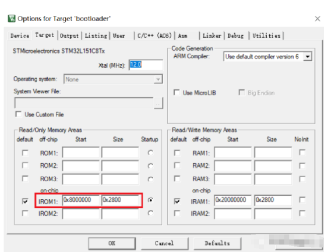
Figure 1 Keil sets the starting address and space
STM32 boot file
;********************* (C) COPYRIGHT 2017 STMicroelectronics ******************** ;* File Name : startup_stm32l151xb.s ;* Author : MCD ApplicaTIon Team ;* DescripTIon : STM32L151XB Devices vector for MDK-ARM toolchain. ;* This module performs: ;* – Set the iniTIal SP ;* – Set the iniTIal PC == Reset_Handler ;* – Set the vector table entries with the exceptions ISR ;* address. ;* – Configure the system clock ;* – Branches to __main in the C library (which eventually ;* calls main()). ;* After Reset the Cortex-M3 processor is in Thread mode, ;* priority is Privileged, and the Stack is set to Main. ;******************************************************************************** ;* ;* Copyright (c) 2017 STMicroelectronics. All rights reserved. ;* ;* This software component is licensed by ST under BSD 3-Clause license, ;* the “License”; You may not use this file except in compliance with the ;* License. You may obtain a copy of the License at: ;* opensource.org/licenses/BSD-3-Clause ;* ;******************************************************************************* ;* <<< Use Configuration Wizard in Context Menu >>> ; ; Amount of memory (in bytes) allocated for Stack ; Tailor this value to your application needs ; <h> Stack Configuration ; <o> Stack Size (in Bytes) <0x0-0xFFFFFFFF:8> ; h> Stack_Size EQU 0x00000400 AREA STACK, NOINIT, READWRITE, ALIGN=3 Stack_Mem SPACE Stack_Size __initial_sp ; <h> Heap Configuration ; <o> Heap Size (in Bytes) <0x0-0xFFFFFFFF:8> ; h> Heap_Size EQU 0x00000200 AREA HEAP, NOINIT, READWRITE, ALIGN=3 __heap_base Heap_Mem SPACE Heap_Size __heap_limit PRESERVE8 THUMB ; Vector Table Mapped to Address 0 at Reset AREA RESET, DATA, READONLY EXPORT __Vectors EXPORT __Vectors_End EXPORT __Vectors_Size __Vectors DCD __initial_sp ; Top of Stack DCD Reset_Handler ; Reset Handler DCD NMI_Handler ; NMI Handler DCD HardFault_Handler ; Hard Fault Handler DCD MemManage_Handler ; MPU Fault Handler DCD BusFault_Handler ; Bus Fault Handler DCD UsageFault_Handler ; Usage Fault Handler DCD 0 ; Reserved DCD 0 ; Reserved DCD 0 ; Reserved DCD 0 ; Reserved DCD SVC_Handler ; SVCall Handler DCD DebugMon_Handler ; Debug Monitor Handler DCD 0 ; Reserved DCD PendSV_Handler ; PendSV Handler DCD SysTick_Handler ; SysTick Handler ; External Interrupts DCD WWDG_IRQHandler ; Window Watchdog DCD PVD_IRQHandler ; PVD through EXTI Line detect DCD TAMPER_STAMP_IRQHandler ; Tamper and Time Stamp DCD RTC_WKUP_IRQHandler ; RTC Wakeup DCD FLASH_IRQHandler ; FLASH DCD RCC_IRQHandler ; RCC DCD EXTI0_IRQHandler ; EXTI Line 0 DCD EXTI1_IRQHandler ; EXTI Line 1 DCD EXTI2_IRQHandler ; EXTI Line 2 DCD EXTI3_IRQHandler ; EXTI Line 3 DCD EXTI4_IRQHandler ; EXTI Line 4 DCD DMA1_Channel1_IRQHandler ; DMA1 Channel 1 DCD DMA1_Channel2_IRQHandler ; DMA1 Channel 2 DCD DMA1_Channel3_IRQHandler ; DMA1 Channel 3 DCD DMA1_Channel4_IRQHandler ; DMA1 Channel 4 DCD DMA1_Channel5_IRQHandler ; DMA1 Channel 5 DCD DMA1_Channel6_IRQHandler ; DMA1 Channel 6 DCD DMA1_Channel7_IRQHandler ; DMA1 Channel 7 DCD ADC1_IRQHandler ; ADC1 DCD USB_HP_IRQHandler ; USB High Priority DCD USB_LP_IRQHandler ; USB Low Priority DCD DAC_IRQHandler ; DAC DCD COMP_IRQHandler ; COMP through EXTI Line DCD EXTI9_5_IRQHandler ; EXTI Line 9..5 DCD 0 ; Reserved DCD TIM9_IRQHandler ; TIM9 DCD TIM10_IRQHandler ; TIM10 DCD TIM11_IRQHandler ; TIM11 DCD TIM2_IRQHandler ; TIM2 DCD TIM3_IRQHandler ; TIM3 DCD TIM4_IRQHandler ; TIM4 DCD I2C1_EV_IRQHandler ; I2C1 Event DCD I2C1_ER_IRQHandler ; I2C1 Error DCD I2C2_EV_IRQHandler ; I2C2 Event DCD I2C2_ER_IRQHandler ; I2C2 Error DCD SPI1_IRQHandler ; SPI1 DCD SPI2_IRQHandler ; SPI2 DCD USART1_IRQHandler ; USART1 DCD USART2_IRQHandler ; USART2 DCD USART3_IRQHandler ; USART3 DCD EXTI15_10_IRQHandler ; EXTI Line 15..10 DCD RTC_Alarm_IRQHandler ; RTC Alarm through EXTI Line DCD USB_FS_WKUP_IRQHandler ; USB FS Wakeup from suspend DCD TIM6_IRQHandler ; TIM6 DCD TIM7_IRQHandler ; TIM7 __Vectors_End __Vectors_Size EQU __Vectors_End – __Vectors AREA |.text|, CODE, READONLY ; Reset handler routine Reset_Handler PROC EXPORT Reset_Handler [WEAK] IMPORT __main IMPORT SystemInit LDR R0, =SystemInit BLX R0 LDR R0, =__main BX R0 ENDP ; Dummy Exception Handlers (infinite loops which can be modified) NMI_Handler PROC EXPORT NMI_Handler [WEAK] B . ENDP HardFault_Handler PROC EXPORT HardFault_Handler [WEAK] B . ENDP MemManage_Handler PROC EXPORT MemManage_Handler [WEAK] B . ENDP BusFault_Handler PROC EXPORT BusFault_Handler [WEAK] B . ENDP UsageFault_Handler PROC EXPORT UsageFault_Handler [WEAK] B . ENDP SVC_Handler PROC EXPORT SVC_Handler [WEAK] B . ENDP DebugMon_Handler PROC EXPORT DebugMon_Handler [WEAK] B . ENDP PendSV_Handler PROC EXPORT PendSV_Handler [WEAK] B . ENDP SysTick_Handler PROC EXPORT SysTick_Handler [WEAK] B . ENDP Default_Handler PROC EXPORT WWDG_IRQHandler [WEAK] EXPORT PVD_IRQHandler [WEAK] EXPORT TAMPER_STAMP_IRQHandler [WEAK] EXPORT RTC_WKUP_IRQHandler [WEAK] EXPORT FLASH_IRQHandler [WEAK] EXPORT RCC_IRQHandler [WEAK] EXPORT EXTI0_IRQHandler [WEAK] EXPORT EXTI1_IRQHandler [WEAK] EXPORT EXTI2_IRQHandler [WEAK] EXPORT EXTI3_IRQHandler [WEAK] EXPORT EXTI4_IRQHandler [WEAK] EXPORT DMA1_Channel1_IRQHandler [WEAK] EXPORT DMA1_Channel2_IRQHandler [WEAK] EXPORT DMA1_Channel3_IRQHandler [WEAK] EXPORT DMA1_Channel4_IRQHandler [WEAK] EXPORT DMA1_Channel5_IRQHandler [WEAK] EXPORT DMA1_Channel6_IRQHandler [WEAK] EXPORT DMA1_Channel7_IRQHandler [WEAK] EXPORT ADC1_IRQHandler [WEAK] EXPORT USB_HP_IRQHandler [WEAK] EXPORT USB_LP_IRQHandler [WEAK] EXPORT DAC_IRQHandler [WEAK] EXPORT COMP_IRQHandler [WEAK] EXPORT EXTI9_5_IRQHandler [WEAK] EXPORT TIM9_IRQHandler [WEAK] EXPORT TIM10_IRQHandler [WEAK] EXPORT TIM11_IRQHandler [WEAK] EXPORT TIM2_IRQHandler [WEAK] EXPORT TIM3_IRQHandler [WEAK] EXPORT TIM4_IRQHandler [WEAK] EXPORT I2C1_EV_IRQHandler [WEAK] EXPORT I2C1_ER_IRQHandler [WEAK] EXPORT I2C2_EV_IRQHandler [WEAK] EXPORT I2C2_ER_IRQHandler [WEAK] EXPORT SPI1_IRQHandler [WEAK] EXPORT SPI2_IRQHandler [WEAK] EXPORT USART1_IRQHandler [WEAK] EXPORT USART2_IRQHandler [WEAK] EXPORT USART3_IRQHandler [WEAK] EXPORT EXTI15_10_IRQHandler [WEAK] EXPORT RTC_Alarm_IRQHandler [WEAK] EXPORT USB_FS_WKUP_IRQHandler [WEAK] EXPORT TIM6_IRQHandler [WEAK] EXPORT TIM7_IRQHandler [WEAK] WWDG_IRQHandler PVD_IRQHandler TAMPER_STAMP_IRQHandler RTC_WKUP_IRQHandler FLASH_IRQHandler RCC_IRQHandler EXTI0_IRQHandler EXTI1_IRQHandler EXTI2_IRQHandler EXTI3_IRQHandler EXTI4_IRQHandler DMA1_Channel1_IRQHandler DMA1_Channel2_IRQHandler DMA1_Channel3_IRQHandler DMA1_Channel4_IRQHandler DMA1_Channel5_IRQHandler DMA1_Channel6_IRQHandler DMA1_Channel7_IRQHandler ADC1_IRQHandler USB_HP_IRQHandler USB_LP_IRQHandler DAC_IRQHandler COMP_IRQHandler EXTI9_5_IRQHandler TIM9_IRQHandler TIM10_IRQHandler TIM11_IRQHandler TIM2_IRQHandler TIM3_IRQHandler TIM4_IRQHandler I2C1_EV_IRQHandler I2C1_ER_IRQHandler I2C2_EV_IRQHandler I2C2_ER_IRQHandler SPI1_IRQHandler SPI2_IRQHandler USART1_IRQHandler USART2_IRQHandler USART3_IRQHandler EXTI15_10_IRQHandler RTC_Alarm_IRQHandler USB_FS_WKUP_IRQHandler TIM6_IRQHandler
First, let’s look at the STM32 boot file. When the MCU is powered on and reset, the entire program jumps to the 0x8000000 address with offset 0, i.e., it is still 0x8000000. But the STM32’s 0x8000000 address stores not the first instruction of the entire chip, but the stack initialization program of the entire chip, as shown in Figure 2.
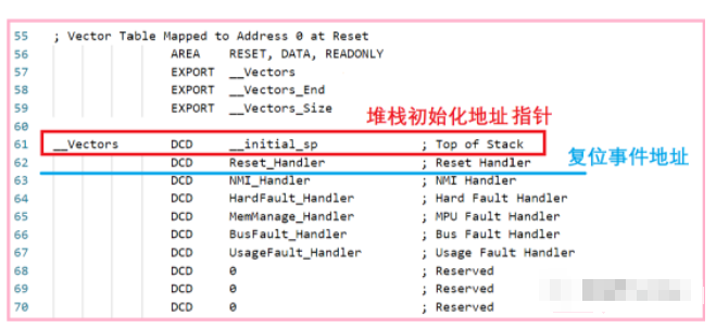
Figure 2 Stack initialization program pointer at 0x8000000 offset 0 address
Since the address space of STM32 is aligned by 4 bytes, the storage space of this stack top pointer is 4 bytes, so the address of STM32 after reset should be 0x8000000 base address offset by 4 bytes, i.e. 0x8000004. As shown in Figure 3.
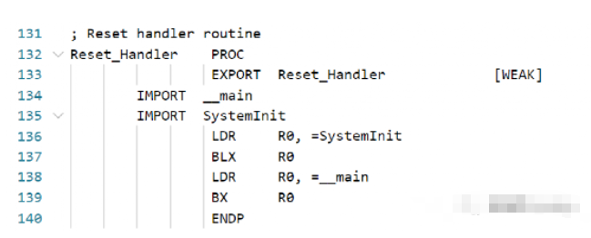
Figure 3 STM32 reset jump address
The program in Figure 3 is very easy to understand, lines 136 and 137, which jump the program to SystemInit, a C function defined in the “system_stm32l1xx.c” file, whose purpose is to specify the start address of the interrupt vector table, which is the “__Vector” in Figure 2. It is defined in the “system_stm32l1xx.c” file. Of course there is a slight difference between the CM3 kernel and CM0 kernel regarding the definition of SCB (System Control Block), CM0 is not discussed in this article, but the interrupt vector table mapping mechanism of CM3 and CM4 is still very similar.
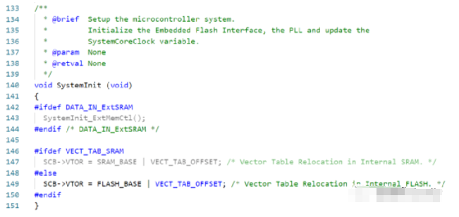
Figure 4 SystemInit function mapping interrupt vector table
In Figure 4 we can see that the address in SCB about Vector is calculated by the symbol FLASH_BASE and VECT_TAB_OFFSET, and we can find the definition about them as shown in Figure 5.
Figure 5 Definition of FLASH_BASE and VECT_TAB_OFFSET
With the calculations in Figure 5, it just so happens that the entire interrupt vector table is mapped to the 0x8000000 address.
FLASH allocation for STM32
A key value, 0x8000000, was mentioned frequently in the previous large section of the article, so where did this 0x8000000 come from? This value is not just a head shot for no reason. As we said before, the memory structure of the ARM system is one of its major features, and this 0x8000000 is the starting address of the entire STM32 built-in FLASH. We can open a copy of the STM32 datasheet and see all the STM32 memory definitions in the memory chapter. As shown in Figure 6.
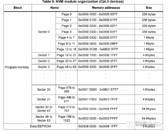
Figure 6 Start address of STM32 internal FLASH
STM32 Bootloader ideas
Putting aside all the advanced features of the Bootloader, we have designed the STM32 Bootloader for two main purposes, the first one is to facilitate program burning and updating, and the second one is to jump (boot) the user application from the Bootloader program. Of these two purposes, program jumping is especially important for the Bootloader, because unsuccessful program jumping will seriously affect the running state of the entire user program. Therefore, how to jump, when to jump, and where to jump, is the focus of the next article.
The previous one, FLASH burning, can be customized according to your own special requirements, as long as the relationship between the address and data specified in the HEX file is strictly installed, there is generally no error.