The technology we have today has advanced massively. It has become a vast part of our daily lives, and with this advancement, the demands for products have grown. However, one thing that hasn’t gone away is the desire to be more productive, which means we are all looking for tools that allow us to get more done in less time.
The hardware inside your processor may matter less and less. Companies are bulking up their web applications with features like voice recognition or virtual assistants. So, as Moore’s law winds down, developers turn to the cloud for new efficiencies and productivity gains. That is why QuickLogic has developed its latest pASIC 2 Family. This family can speed up and enhance cloud-based applications depending on network connections. It includes embedded software.
The pASIC 2 Family depends on the same foundation as the QuickLogic pASIC 4 Family, introduced in 2013. The QuickLogic pASIC 4 Family is the industry’s most widely adopted chip. It is essential for general-purpose processing control of radiofrequency and data communication signals. In addition, its flexible, modular design has been in use in hundreds of millions of units by Ebics
Evolution of electronics
This evolution has been made possible by the development of integrated circuits. The first integrated circuit started working in 1962, and the first practical model was released a few years later.
In the early 1970s, transistors were cut into a semiconductor wafer, diced into smaller pieces, and placed onto a printed circuit board (PCB). Starting with a single chip has led to today’s multi-chip modules.
The earliest models of integrated circuits were simple, short-range, and low-speed. However, they were more power-efficient than discrete components (e.g., batteries or capacitors). As a result, they were often helpful in inexpensive products sold to the public.
In the 1980s and 90s, improved transistors and processes allowed higher speed and more sophisticated circuits. As a result, products require more features and longer battery life. At the same time, they simultaneously enhanced performance. At the same time, demand for simpler designs continued. As a result, it drove costs down and led to the development of modern microprocessors.
In the early 2000s, embedded processors were explicitly for applications in which space was premium. Therefore, they required a very low-cost solution with high reliability. Additionally, the primary benefit of this approach is that it frees up space on larger systems for more complicated applications.
In an embedded processor, analog components are integrated directly onto the chip, allowing for a single point of control. Today, we can also put an entire computer system on a single chip, as cloud computing has become dominant. As a result, pressure is put on semiconductor manufacturers to find ways to reduce costs. This provides the best performance at the lowest price has been the order of the day. It is true for commercial and military radar systems across several sectors. They include automotive, medical, and aerospace.
How does it work?
To understand how this technology works, we will compare it to traditional hardware solutions in two areas:
Processing performance versus power consumption and size.
Regarding processing performance, the pASIC chip has a built-in digital signal processor. As a result, it can perform as many simultaneous calculations within a given time frame as a multi-core, high-end desktop processor could. For example, the pASIC chip can simultaneously process data requests from user and server applications. So, it saves on network bandwidth needs. As a result, this is true regardless of the application’s data size or the size of user input (e.g., text, audio).
The pASIC 2 Family has energy efficiency in mind. Low power consumption features help reduce overall operating costs by minimizing battery usage, extending device life, and reducing maintenance costs, especially for industrial products.
QuickLogic pASIC 2 History
In 2012 QuickLogic released the first pASIC product, the pASIC 1 Family. As a result, the first processor aimed at applications requiring general-purpose processing control of RF and data communication signals (GPRC). So, this flexible, modular design has proven itself in a fantastic variety of applications in such areas as cell phones, wireless backhaul, wireless broadband over fiber, and – last but not least – to control power for LTE base stations. The pASIC 1 Family is available in several configurations leading to optimized performance for different applications.
In 2015, the pASIC 1 Family added a new generation of equipment—the QuickLogic pASIC 2 Family. In addition, the design upgraded to maintain its high level of flexibility, advanced IP, and support higher core counts, resulting in performance-per-watt on par with competing products. However, compared to the competition, the QuickLogic pASIC 2 has several distinct advantages:
The QuickLogic pASIC 2 comes in the C4 (4Mb L1 cache) and C6 (6Mb L1 cache). The C4 has a maximum clock frequency of 1.8 GHz, while the C6 can reach 1.9 GHz. Moreover, the memory interface is DDR3L-1600 (C4) and DDR3L-1866 (C6), which allows for data rates of up to 2400 MT/s. In addition, the pASIC 2 Family offers the same pin-out and fanout as the
QuickLogic has also equipped the pASIC 2 Family with its PSOC-based software development environment and a rich set of libraries, including a comprehensive application program interface (API) for RF, front-end processing, and data communications. The advantage of an API approach is that the programmer does not need to program the hardware directly. Instead, the programmer uses high-level commands to control the hardware functions. So, these commands may be in a high-level language such as C or C++, or they may be very low using command line tools or embedded scripts.
QuickLogic pASIC 2 overview
The QuickLogic pASIC 2 can help build an application with several different layers, from the control of a single radio front end up to a complete base station. Additionally, the QuickLogic pASIC 2 family brings together the expertise of the RF, baseband, and applications teams at QuickLogic. As a result, it consists of the same foundation as its predecessor, the widely popular QuickLogic pASIC 4 Family.
The throughput of a computing platform typically depends on how fast we can move data into and out of memory. So, this directly impacts how many instructions can be executed per second (IOPS). The pASIC 2 Family supports DDR3L-1600, up to ten times faster than the DDR2-800 used in the pASIC 1.
The QuickLogic pASIC 2 family consists of a base station processor (BSP) and a switch. Also, the BSP usually connects to RF front ends (power amplifiers, filters, etc.) and data communication interfaces. A few of these connections are standardized such as Ethernet, USB, and WiFi. Other connections are proprietary but can be easily adapted to existing devices: LTE power control via USB (e.g., LTEBase-USB) or Bluetooth to a SmartPlug.
The QuickLogic pASIC 2 Family comes with rich software, Flash programming, and firmware libraries. Additionally, it has a PSOC-based real-time operating system (RTOS) to provide the computing capacity for message passing and networking. In addition, the QuickLogic pASIC 2 comes with lots of connectivity options for data communication interfaces such as Ethernet, USB, and WiFi, which enables it to incorporate into wireless base station solutions easily.
The main benefit of the architecture is that all tasks can run on the same hardware platform. So, this helps save significant development costs such as cost-intensive board changes when adding new features.
Features
High design security:
All processor control signals are protected by security fuses located on the motherboard. So, this prevents unauthorized hardware modifications like hacking or malicious system software (malware).
5.0V PCI compliant:
The QuickLogic pASIC 2 uses standard PCI slots. Therefore, PCI cards can be inserted into the BSP and used for PCIe connectivity. As a result, the QuickLogic pASIC 2 is also fully supported by the various manufacturers of BSPs.
I/O pin-compatibility:
Pin-compatible I/Os can help connect the QuickLogic pASIC 2 with other ASICs like Intel.
Low standby power operation:
The QuickLogic pASIC 2 can operate at 3.3V and 5.0V, and it supports both 1.5V and 3.3V memory operation on the same device. As a result, this means that designers have a wide range of power options; they can select either reduced power consumption or higher performance for different application requirements on the processor itself. However, this is not enough to achieve the best overall power consumption in a wireless base station: other components such as RF modules, LED drivers, and backhaul interfaces in a base station also impact power consumption.
Individually-controlled I/O pins:
Input and feedback registers control all processor control signals individually and enable on/off each pin. So, this ensures that the processor operates within its design specifications regardless of how the BSP is powered or what other, conflicting I/Os might be present on the PCB.
IEEE Standard JTAG:
The QuickLogic pASIC 2 BSP has full IEEE Standard JTAG boundary-scan capability. As a result, this means the programmer doesn’t need to carry out all controller testing on the board.
High synthesis gate utilization:
The pASIC 2 uses logic cells, not full logic circuits, to easily split into smaller circuits. So, the result is very efficient utilization of the silicon area.
Complex functions in a single logic cell are a significant design benefit of the QuickLogic pASIC 2. Additionally, the processor can process complex functions like 8-bits per input, with 16 inputs. Additionally, we can accomplish this with a single logic cell that can simultaneously switch up to four of these inputs.
Highly scalable:
We can scale the QuickLogic pASIC 2 to hundreds of millions of transistors. As a result, the gate-level netlist simulation tool enables scalable designs up to 2.5 V on 28 nm process technology.
Pin-out maintainable and 100% routable:
the QuickLogic pASIC 2 pin-out does not move. So, each pin can be re-routed or moved to other pins. For example, wireless base station designs often have several pins used for different functions. As a result, re-using one or two pins from a pair can save a significant area.
3-layer metal:
the pASIC 2 sits on a 3-layer ViaLink process, allowing the latest metal via technology for small die sizes.
225 I/Os:
the QuickLogic pASIC 2 BSP has 226 I/Os, and additional functionality, such as 3-layer metal, PCI, and a real-time operating system (RTOS), can be added.
Sixteen thousand usable PLD gates:
the QuickLogic pASIC 2 has 16,000 usable gates.
9,000 usable ASIC gates:
the QuickLogic pASIC 2 has an estimated 9,000 usable gates.
Over 200 MHz 16-bit counter speeds:
the pASIC 2 can reach over 200 MHz with a 16-bit counter.
Efficient Verilog/VHDL synthesis:
the QuickLogic pASIC 2 is a Verilog/VHDL synthesizable device, which means we can quickly program it into a custom design BSP.
Design tools produce fast:
the QuickLogic pASIC 2 has a design tool on standard PC systems, including Windows and Linux. As a result, this allows designers to see the processor running their device in real-time or examine detailed device behavior.
Flexible logic cell:
the QuickLogic pASIC 2 uses a relatively small number of logic gates. As a result, this allows the BSP to split into two or three smaller circuits. In turn, it increases the efficiency of logic cell utilization and improves performance.
Abundant, high-speed interconnect:
the QuickLogic pASIC 2 has a high-speed interconnect that removes the need for manual routing of signals.
PIN Description
1. GND: General Purpose Digital Ground. This pin is a ground for the logic section of the chip. As a result, it is not connected to the board’s ground plane and therefore is a true digital ground.
2. VCC: 3.3V Core Supply. This pin is a 3.3 V power supply for the digital core of the QuickLogic pASIC 2 device.
3. I/O: Input/Output. Connect to the inputs or outputs of your design.
4. High-drive input: This pin is a high-drive input pin. It can drive up to 5 mA with 3.3 V at a maximum of 10% duty cycle.
5. I/GCLK: I/O to Global Clock. This pin provides an I/O connection to the system clock for the QuickLogic pASIC 2 device.
6. I/ACLK: I/O to Access Clock. This pin provides an I/O connection to the system clock on-chip core 2 and controller.
7. STM: System Test Mode. This pin provides a dedicated input to allow the core to enter the system test mode. As a result, the JTAG boundary scan test interface can activate.
8. TDO: Test Data Out. This pin is an output-only pin that provides data from the core scan chain during the boundary scan test mode.
9. TMS: Test Mode Select. This input-only pin selects the test operation for the QuickLogic pASIC 2 device during the boundary scan test mode.
10. TCK: Test Clock. This pin comes as a system clock source during the JTAG boundary scan test mode.
11. TRSTB: Reset Bit. This input-only pin is helpful as a test reset source for the QuickLogic pASIC 2 device during the boundary scan test mode.
THE ULTIMATE GUIDE TO XILINX FPGA, SERIES, AND ALL DETAILS
AC Characteristics
1. The timing values listed in the datasheet are valid for VIN = 4.5V to 5.5V and VCC = 3.3V ±10% unless otherwise noted.
2. If the external clock frequency is less than 500 MHz, the datasheet includes a recommended tolerance of ±5%. However, if it is greater than 500 MHz, the datasheet consists of a recommended tolerance of ±10%.
3. We measure the frequencies listed in the datasheet from an AC power source with output connected to VCC and ground. Additionally, a typical PC AC adapter rates at 100% efficiency with 500 Hz ripple frequency.
4. For ease of comparison, AC timing parameters are available for both 3V and 5V operations without regard to operating temperature ranges specified from one datasheet to another.
PCI Interface
The primary function of any PCI controller is to transfer information at high speeds between a host computer. Examples include a microprocessor, and peripheral devices that may connect to it. A clock signal typically derived from an external crystal oscillator determines the transfer rate. Additionally, on-chip peripherals can also use this same clock signal. In this case, however, it should be considered a source for other parts of the system because its frequency is variable and therefore not suitable for accurate timekeeping purposes. In addition, you must appropriately adjust the clock signal for maximum performance and stable software.
For this reason, QuickLogic pASIC 2 BSP has a full on-chip PCI core that supports high-speed data transfers between the processor and various system buses. In addition, the QuickLogic pASIC 2 BSP also includes support for an external clock source. As a result, this may provide a base clock signal for the on-chip peripherals and other devices. Still, the primary purpose of the external clock signal is to provide a reference for an independent timing engine that allows data transfers at up to 1 GT/s (1 billion bit/s). As a result, the QuickLogic pASIC 2 BSP has a true PCI core that supports high-speed data transfers and can create a high-speed external bus that can operate in compliance with the PCI Local Bus Specification, revision 2.2.
The datasheet shows the initialization timing and reads/write signal through pin descriptions. Additionally, timing values are supplied both as a reference design and in tabular format as part of the timing section of the datasheet. In addition, many timing parameters are supplied with an example design to illustrate how they may help implement an on-chip peripheral that operates at 1 GT/s.
Application field
Artificial Intelligence:
A wide range of applications for a QuickLogic pASIC 2 BSP is possible in artificial intelligence. So, performing intensive arithmetic operations in parallel allows processors to help with high performance and complexity.
5G Technology:
5G communication systems, such as PCS, are now deployed and critical to high-speed wireless data transfer. For example, the QuickLogic pASIC 2 BSP supports high-speed operations at up to 1 GT/s through on-chip peripherals.
Cloud Computing:
The PCS 5G systems will provide wireless data transfer greater than 100G in the form of an Internet-of-Things (IoT) compound system. However, the IoT systems will require high-speed processing when multiple IoT devices work together to form a data network.
Wireless Technology:
In a wireless system, communication must work with a very high level of real-time speed. Additionally, these systems must operate with very low latency and maximum transmission rate that we can achieve through the QuickLogic pASIC 2 BSP.
Robotics:
Robotics requires a high-speed network and complex computational data processing. In many cases, the robotics software must support new algorithms and data flow patterns that we can achieve through a fast processor and high-speed peripherals such as memory controllers, acceleration buses, and video interfaces.
Industrial Control:
Industrial control systems are very advanced and require a very high level of speed. In addition, these systems monitor and control multiple devices. As a result, the results must process in real-time.
Medical Equipment:
Medical equipment is helpful in various applications. For example, these devices are often beneficial to monitor and measure numerous variables that we must analyze in real-time.
Military Equipment:
Military systems require high security, reliability and accuracy, and computing power with low latency and fast response time. Therefore, the QuickLogic pASIC 2 BSP FPGA can support these requirements because it includes on-chip peripherals which can operate at 1 GT/s through the integrated PCI bus interface.
A DETAILED GUIDE TO INTEL’S ALTERA FPGA
Limitations on using the QuickLogic pASIC 2
1. The QuickLogic pASIC 2 BSP is not intended for use on applications that require high-quality timing or tight synchronization to an external clock signal. As a result, the QuickLogic pASIC 2 BSP only supports PCI registers necessary for essential operation. In addition, it does not support advanced features such as configurable latency, target and initiator modes, or burst and interleaved transfers. However, if these features are required, they must go through the system designer using off-chip components such as programmable logic or application-specific integrated circuits (ASICs).
2. The QuickLogic pASIC 2 BSP is not intended for use on applications that require tight synchronizing an external clock signal with the on-chip core. For example, the QuickLogic pASIC 2 BSP may be helpful with an external clock. However, the processor core cannot be programmed to synchronize to this clock. Therefore, we should consider the on-chip peripheral clocks, which may not match the external clock.
3. The QuickLogic pASIC 2 BSP programmable logic array (PLA) is necessary for only a test engine or a control circuit. It may help to control external devices. In this case, the devices should be designed to interface with this PLD at up to 1 GHz frequencies. For example, the PLD may be used to clock low-power parts of a system, such as a CPU. However, we should consider the PLD clock a possible source of noise in the system, and it may affect the performance of other components that also use this clock.
How to obtain software development tools for the QuickLogic FPGA platform
The Magma Design Automation uses the QuickLogic pASIC 2 system-on-chip (SoC) software development toolset. It includes the QuickLogic ISE design environment, host PCLink and PCI Express (PCIe) LinkPort product support software and an evaluation version of QuickLogic Lab that provides two virtual FPGA devices for prototyping.
Software support for the QuickLogic pASIC 2 BSP can divide into two major software groups: hardware control and hardware modeling.
Hardware Control Software
At the heart of QuickLogic ISE is the hardware control portion of the software tools. When used with QuickLogic pASIC 2 BSP, this includes all modules used to generate a design for the QuickLogic pASIC 2 BSP and any host-level software required for communication with the device. Hardware support for QuickLogic pASIC 2 BSP allows customization of various FPGA structures. This includes configuration and routing resources, multiplexers and latches, and memory blocks. Additionally, hardware support also provides access to all on-chip peripherals via pins exposed on a PCI Express (PCIe) bus.
With this support, QuickLogic pASIC 2 BSP users can create designs fully compliant with IEEE 1149.1-1990 and IEEE 1149.1-2004. They include all timing requirements associated with the Host-PCI standard.
The QuickLogic ISE software development toolset includes a variety of host PCLink and PCIe LinkPort software products that enable communication between the host PC and the hardware core of QuickLogic pASIC 2 BSP. In addition to the host PCLink and PCIe LinkPort products available for QuickLogic pASIC 2 BSP. Additionally, the QuickLogic ISE software environment also contains various components that provide functionality TPC/E, test generation, verification, and debug.
pASIC 2 Family Devices
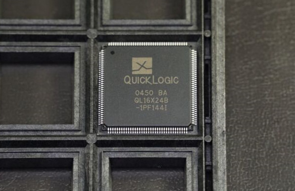
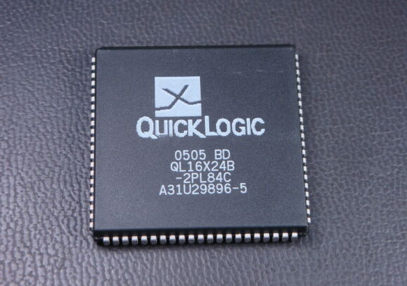
| QL2009-ZPQ208C | QL2009-1PQ208M | QL2007-XPL84I | QL2007-1PF144I | QL2005XLT-84C |
| QL2009-ZPQ208 | QL2009-1PQ208I | QL2007-XPL84C | QL2007-1PF144C | QL2005-QPF144C |
| QL2009-XPQ208I | QL2009-1PQ208C | QL2007-XPF144I | QL2007-0PQ208I | QL2005-IPQ144C |
| QL2009-XPQ208C | QL2009-1PF144I | QL2007-XPF144CC | QL2007-0PQ208C | QL2005-IPF144C |
| QL2009-XPF144I | QL2009-1PF144C | QL2007-XPF144C | QL2007-0PL84I | QL2005-2PQ240C |
| QL2009-XPF144C | QL2009-1PB256M | QL2007-XPE144I | QL2007-0PL84C | QL2005-2PQ208I |
| QL2009-XPF144 | QL2009-1PB256I | QL2007-XPE144C | QL2007-0PL144C | QL2005-2PQ208C |
| QL2009-XPB256I | QL2009-1PB256C | QL2007-QPQ208C | QL2007-0PF144I | QL2005-2PL84I |
| QL2009-XPB256C | QL2009-0PQ208M | QL2007-IPQ208C | QL2007-0PF144C | QL2005-2PL84C |
| QL2009-2PQ208M | QL2009-0PQ208I | QL2007C-1PQ208C | QL2005-XPQ208I | QL2005-2PL84 |
| QL2009-2PQ208I | QL2009-0PQ208C | QL2007-2PQ208I | QL2005-XPQ208C | QL2005-2PF144I |
| QL2009-2PQ208C | QL2009-0PL144C | QL2007-2PQ208C | QL2005-XPQ144C | QL2005-2PF144C-679 |
| QL2009-2PF144I | QL2009-0PF144I | QL2007-2PL84I | QL2005-XPL84I | QL2005-2PF144C |
| QL2009-2PF144C | QL2009-0PF144C | QL2007-2PL84C | QL2005XPL84-I | QL2005-1PQ208I |
| QL2009-2PB256M | QL2009-0PB256M | QL2007-2PF144I | QL2005-XPL84C | QL2005-1PQ208C |
| QL2009-2PB256I-1446 | QL2009-0PB256I | QL2007-2PF144C | QL2005-XPF144I | QL2005-1PL84I |
| QL2009-2PB256I | QL2009-0PB256C | QL2007-1PQ208I | QL2005-XPF144C | QL2003-XPF144C |
Conclusion
In conclusion, the QuickLogic pASIC 2 Family of FPGA SoCs offers a comprehensive set of tools. They help software developers to create high-performance, high-accuracy devices.
The QuickLogic pASIC 2 BSP is a single-core processor that includes an on-chip PCI Express (PCIe) interface and supports PCI Local Bus Specification. QuickLogic pASIC 2 BSP typically runs at up to 1 GHz. In addition, the QuickLogic pASIC 2 BSP can operate in either generic or standard configurations. In addition, it provides flexibility for future application development after releasing the QuickLogic pASIC 2 BSP.