I. The principle and application of optical thin film.

Simply put, the whole physical basis of optical thin film is the interference of light.
The so-called optical film must first be thin and then produce a certain optical effect.
The degree of “thinness”.
A) Qualitative description, the thickness of the optical film should be comparable to the wavelength of the incident light.
B) Physical meaning: a film layer capable of producing interference phenomena.
Thin film optics is an important branch of physical optics, which studies the reflection, transmission and absorption of light by a film layer, as well as the phase characteristics and polarization characteristics.
When light passes through the layered medium, the reflected light and transmitted light from different interfaces produce light interference phenomena in the direction of light incidence and reflection. Using this interference phenomenon, the interference of light can be artificially controlled by changing the material and its thickness and other characteristics to achieve the redistribution of light energy as needed.
Optical films can be divided into two main categories.
A) Optical films: Light propagates across the film.
(B) Thin-film waveguide: light propagates within the film along the direction parallel to the film interface.

The role of optical films in optical systems.
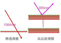
A) To improve optical efficiency and reduce stray light, such as reflection reduction film (transmission enhancement film), high reflection film, etc.
B) to achieve beam adjustment or redistribution, such as beam splitting film, color separation film, polarization beam splitting film, etc.
C) improve system signal-to-noise ratio through wavelength selective transmission. Such as narrow band and band pass filters, long wave pass or short wave pass filters.
D) Realize some special functions, such as ITO transparent conductive film, protective film, etc.
Industries related to optical thin film technology.
A) Coated eyeglasses
B)Curtain wall glass
C)Filters
D)Optical lenses
E)ITO film
F)Car light, cold light mirror, stage lighting filter
(G) laser systems
H)Optical communication devices
I)Projection display
J)Machine vision
II. Classification of optical films
- Anti-reflective film, also called transmissive film (AR)
l The role of the transparency-enhancing film.
A) Increase the transmittance of optical system
B) reduce stray light
C) increase the action distance
D) improve image quality
l Types of transparency enhancement film: A) Single point reduction
A)Single point reduction
B)Wide-band reflection reduction
C)Double-band reflection
D)Wide angle reduction
Application Example 1: Magnesium Fluoride Anti-Reflection Membrane

The reflectivity is 1.26% at 510nm.
The reflective reduction film is a 1/4 wave sheet at 510nm, a 0.725 1/4 wave sheet at 700nm, and a 1.275 1/4 wave sheet at 400nm.
Application example 2: Double-layer reflective film

With both materials it is possible to reduce the reflectivity to a much lower level (close to 0).

Application example 3: Adding a half-wave layer to an anti-reflective film

Adding a half-wave sheet between the two layers of the design does not change the reflectivity of the film layer, but can increase the wavelength bandwidth.
For example, the addition of ZrO2 with a refractive index of 2.15 is shown in the figure above.
l Main indicators of the enhanced transmission film.
A) Wavelength band used
B)Angle or range of angle to be used
C) residual reflectance requirement
D)Using environment
E) In the laser field there are also low absorption, laser threshold and other requirements
- Beam splitting film
In general, beamsplitting films are always used at an angle, and there are two types of 45 degree beamsplitting films commonly used, one is neutral beamsplitting film (depolarizing NPBS) and the other is polarizing beamsplitting film (PBS).
Neutral beamsplitters are available in flat type and prismatic type. prismatic type is generally used for PBS, flat type has image dispersion problem and is generally only used in low to medium requirement optical devices.
Beamsplitters can be divided into metal beamsplitters and dielectric beamsplitters according to the coating material.
l Advantages of metal beamsplitter.
A) Good neutrality
B)Wide spectral range
C) small polarization effect
D)Simple fabrication
l Disadvantages of metal beamsplitter.
A) Large absorption
B) Low laser threshold
l Advantages of dielectric beamsplitter.
A) small absorption, almost negligible
l Disadvantages of dielectric beamsplitter: A
A) narrow spectral range
B)Significant polarization separation
C) Angle effect is obvious
- reflective film
Reflective films are equally important in the application of optical systems.
Pure metal reflective film: can meet the requirements of most optical instrument reflective systems.
Full dielectric reflective film: can have the maximum reflectivity and the minimum absorption, thus has more applications in laser systems and highly demanding optical systems.
3.1 Metal reflective film
Principles for the selection of metal film materials.
Use of waveband
Reflectivity index
Use environment
Production cost
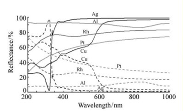
Commonly used metal film reflective materials include Al, Au, Ag, Pt, Cu, etc.
Al, the most commonly used, can be used in UV, visible and IR.
Ag, the highest reflectivity, but poor stability.
Au, commonly used in infrared, good stability.
Pt, stable and strong performance.
3.2 Full-media reflective film
Theoretically, the reflectivity can be infinitely close to 100% by increasing the number of layers of the film system, but in practice, due to the absorption and scattering of the film layer, when the film layer reaches a certain number of layers, continue to add plating, the reflectivity will no longer improve, and even due to the increase of absorption and scattering, the reflectivity decreases.

- Filter film
Generally, the film that changes the nature or color of the light beam is called filter film, and the common ones are interference cutoff filter and bandpass filter.
4.1 Interference Cutoff Filters
Interference cutoff filters require high transmission of light in a certain wavelength range and cutoff of light that deviates from the wavelength range.
Typical cutoff filters are short-pass filters (allowing only short-wave light to pass) and long-pass filters (allowing only long-wave light to pass), which are multilayer dielectric films with a periodic structure consisting of alternating high- and low-refractive-index layers.
Several important indicators of interfering cut-off filters are
l The wavelength at which the transmission curve begins to rise (fall) and the permissible slope at which this curve rises (or falls).
The average transmittance of the spectral width in the high transmittance band and the minimum transmittance allowed in this transmittance band.
The spectral width of the reflectance band (suppression band) with low transmittance and the maximum transmittance allowed in this range.

4.2 Band-pass filters
A filter with a cutoff zone on both sides of the transmission band of the spectral characteristic curve is called a bandpass filter.
Band-pass filters are an important class of optical thin film components, which are widely used in chemistry, spectroscopy, laser, astrophysics, fiber optic communication, biology and other fields.
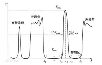
The spectral curves of bandpass filters prepared by light wave interference principle are shown in the figure below. The spectral transmission area near the wavelength λ0 in the figure is called the passband of the filter, usually with cutoff areas on both sides, and there may be bypass bands around the cutoff areas, which usually need to be eliminated by colored glass, absorber film or cutoff filters.
l The main characteristic parameters of bandpass filters are
① λ0: the central wavelength, also called the peak wavelength.
② Tmax: transmittance at λ0.
③ 2Δλ0.5: half-width, which is the wavelength width of the passband at which the transmission peak is half of the peak.
④ 2Δλ0.1: decimal width, which is the wavelength width of the passband at which the transmission peak is 10% of the peak.
⑤ 2Δλ0.1/2Δλ0.5: waveform coefficient, which characterizes the degree of rectangularization of the passband.
⑥ 2Δλ0.5/λ0: relative half-width, sometimes denoted as HW.
(vii) Tmin: the minimum transmittance of the suppressed band, i.e., the background transmittance.
⑧ Tmin/Tmax: the suppression rate.
⑨ λ3-λ4: long-wave cutoff range.
⑩ λ1-λ2:: short-wave cutoff range.
According to the spectral characteristics of bandpass filters can be divided into: narrowband filters and broadband filters, but this division does not have a clear boundary, usually the relative half-width of not less than 20% of the filter is called broadband filters.