Analog-to-digital converter performance parameters are an important reference for determining the performance of the device, so understanding the performance parameters is essential for hardware selection.
Quantification error and resolution
The resolution of A/D converter is customarily expressed by the number of bits of output binary or the number of BCD code bits, i.e., the 4-bit binary number is used to represent the 10 digits from 0 to 9 in the 1-bit decimal number. Resolution is generally 8-bit, 10-bit, 12-bit, 14-bit, 16-bit, 24-bit, according to the formula digital minimum change 1LSB = Vref/2^nVref for the ADC reference voltage, the higher the resolution then the more accurate the voltage can be distinguished.
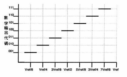
The quantization error and resolution are unified. The quantization error is the error caused by the discrete value (quantization) of the wired digital to the analog digital. The quantization error is the basic error. For example, a 3bit ADC with a reference voltage of 1V, then the signal of voltage 0 ~ 0.125V can be represented by 000, but the individual levels within 0 ~ 0.125V will be indistinguishable, which is the quantization error brought about after digitization. Therefore, the quantization error is theoretically one unit resolution, i.e. ±1/2 LSB. increasing the resolution can reduce the quantization error.
Conversion Accuracy
A/D conversion accuracy reflects the difference between an actual A/D converter in quantization value and an ideal A/D converter for analog/digital conversion, which can be expressed as absolute error or relative error, similar to the definition of general test instruments.

Conversion time, conversion rate and sampling time
The conversion time is defined as the time required for the A/D converter to complete a complete measurement, i.e., the time from the addition of the signal at the input to the appearance of the corresponding digit at the output. The conversion time of integral AD is milliseconds, which is low speed AD, while that of successive comparison AD is microseconds, which is medium speed AD, and fully parallel/serial parallel AD can reach nanoseconds. Usually, the conversion rate is the reciprocal of the conversion time. Sampling time is another concept, which refers to the interval between two conversions. To ensure that the conversion is done correctly, the sampling rate must be less than or equal to the conversion rate. Therefore, it is customary to equate the conversion rate to the sampling rate in numerical terms is also acceptable. The common units are ksps and Msps, which means thousand/million samples per second.
Power Supply Rejection Ratio
The power supply rejection ratio (PSRR) reflects the A/D converter’s ability to suppress changes in the supply voltage, and is expressed in terms of the range of supply voltage changes corresponding to ±1LSB changes in the data when the supply voltage is changed.
Signal-to-noise ratio
Signal-to-noise ratio is the ratio of signal power to total noise power (including quantization noise, thermal noise, white noise, and other circuit noise). The SNR power noise is for the entire Nyquist sampling interval, which decreases slightly in the second Nyquist interval, but is almost constant overall. SNR = 6.02N + 1.76dB considering only quantized noise, considering noise within the Nyquist bandwidth, but in practice the effective bandwidth of the signal is often less than fs/2, so if a digital filter is then used in the post-stage to filter out the out-of-bandwidth noise, this can improve the signal-to-noise ratio, and the formula is shown below.

The signal-to-noise ratio is affected by the input signal frequency, sampling frequency, ADC quantization bits and input signal amplitude, which is proportional to the input signal amplitude. Increasing the sampling frequency of the ADC and increasing the number of quantization bits of the ADC can effectively improve the signal-to-noise ratio.
Signal-to-noise ratio
The SINAD is obtained by calculating the ratio between the root mean square of the input signal and the root sum of the squared values of all noise and distortion components in the FFT analysis except the DC component. the SINAD value is a particularly useful performance indicator because it incorporates the effects of all noise, distortion and harmonics introduced by the A/D converter SINAD = (S+N+D)/(D+N).
General principles of A/D converter selection
The following issues need to be considered when selecting an A/D converter.
(1) The system to which the A/D converter is applied, the number of bits of output data (resolution), the accuracy and linearity to be achieved by the system.
(2) The input signal range, polarity, and signal drive capability of the input A/D converter.
(3) The requirements for the digital code of the converter output and its logic level. Is it required with output latch or tri-state gate? Is it through a computer interface circuit? Is an external clock, internal clock or no clock? Does the output code need to be binary code or BCD code? Is it serial, or parallel?
(4) Will the system operate under static or dynamic conditions? What are the bandwidth requirements? What is the required conversion time of the A/D converter? What is the sampling rate? Is it a high-speed application or a low-speed application?
(5) Is the required reference voltage internal or external? Is it fixed or variable?