The Pound-Drever-Hall (PDH) technique, an active frequency locking technique, is one of the best performing means of laser frequency stabilization systems available and was first proposed by R.V. Pound, Ronald Drever and John L in 1983. Laser systems using Fabry-Perot (F-P) cavity frequency stabilization are the most common method of frequency stabilization. When a laser is injected into an F-P cavity, it is reflected, transmitted or absorbed, and the closer the length of the cavity is to half the exact wavelength of the laser, the farther the laser’s energy is transmitted. Unfortunately, the continuous variation of laser frequency and cavity length depends on a series of factors, such as ambient temperature, injection current and quantum fluctuations.PDH locking uses the light reflected from the resonant cavity to generate an error signal to fine-tune the resonant cavity length or laser frequency, thus accomplishing some matching of cavity length and laser frequency for maximum long-range transmission.

According to the block diagram to briefly explain the PDH technology, the laser output frequency ω laser, and then through the EOM crystal (electric-optical modulator) electro-optical modulator, the laser light field for RF electro-optical phase modulation, and then the modulated laser signal through the polarization beam splitting prism (PBS) and quarter wave piece (λ/4) into the optical cavity, and then Through the reflection to reach the photodetector, the polarization beam splitting prism (PBS) and quarter wave piece (λ/4) is to let the cavity reflect light into the detector. The reflected light signal is then phase-demodulated to get the frequency detuning information in the reflected light and generate an error signal, which is then processed by a low-pass filter and PID (proportional integral circuit) and fed back to other response devices such as the laser’s piezoelectric ceramic or acousto-optic modulator for frequency compensation, which ultimately achieves locking the ordinary laser onto the ultra-stable optical cavity. The theoretical details of the PDH technique can be found in several review papers and dissertations. To achieve PDH locking, a number of specialized and custom electronic instruments are required, including signal generators, mixers, and low-pass filters. moku’s laser locking box integrates all of the PDH electronic instruments for ease of use in providing highly accurate laser frequency stabilization.
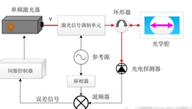
Figure 1: PDH frequency stabilization system schematic
Experimental setup
Moku’s laser lock box integrates a waveform generator, mixer, low-pass filter and a dual cascade PID controller for PDH lock. By adjusting the length of the laser cavity, the amplitude of the reflected light can be monitored and the PDH signal displayed in real time on the screen. The user can lock the laser at any over-zero point with a single tap.

Figure 2: Main User Interface Moku:Lab Laser Lockbox
In an example setup, the outgoing light from the Prometheus laser (Innolight, 20NE) is modulated by an electro-optical modulator (EOM, iXBlue, NIR-MPX-LN-0.1) and irradiated by a three-mirror annular cavity (168 mm, i.e., 1.78 GHz FSR), which has a cavity linewidth of 190 kHz. reflected light is fed into the coupler Instant reflection capture. Two photodiodes (PD, Thorlabs, PDA05CF2) are used to detect the transmitted and reflected light from the cavity. the signals detected on the PD are fed to input 1 (mixer input, AC coupling resistor 50 Ω) and input 2 (monitor, DC coupling resistor 50 Ω) of the Moku:Lab. Using Moku’s laser-locked box waveform generator, a 500 mVpp fundamental oscillation (LO) signal was generated at a frequency of 3.0 MHz. The LO signal is then output from output 2 of the Moku:Lab and driven to the EOM through a bias (minicircuits, ZFBT-6G+).The reflected response signal from the optical cavity is demodulated with the LO digital signal waveform, and here we use a digital mixer and a fourth-order digital low-pass filter with an angular frequency of 300.0 kHz. The phase shift of the LO signal at the mixer is adjusted by scanning the laser frequency of the cavity resonance and adjusting the phase delay until the error signal peak-to-peak voltage (slope) is maximum.
The fast PID controller has an integrator unit gain frequency (0 dB point) of 5.8 kHz and an initial integrator saturation angle of 100 Hz. Output 1 of the fast PID is then connected directly to the laser’s piezoelectric ceramic to drive the laser frequency. In scanning mode, this output also generates a ramp signal to find the cavity resonance. The low frequency PID controller has a proportional gain of -32.2 dB and an integrator crossover frequency of 200 mHz. output 2 from Moku:Lab comes out and is split into two paths via Bias-Tee, one to the EOM and one to the laser’s temperature control BNC interface. A 20 dB attenuation (Minicircuits, HAT-20+) was placed on this laser temperature actuator to reduce its sensitivity.

Figure 3: Experimental setup of PDH technology built with Moku:Lab
Moku Series Parameters
Demodulation frequency range 1mHz-600MHz
Number of input channels 4
Number of output channels 4
Sampling frequency single channel ≥5 GSa/s
Resolution 10 bits
Maximum input voltage 40Vpp(1MΩ)
Phase shift accuracy 0.001°
Dynamic reserve >120dB
Minimum time constant ≤ 30 ns
Integrated PID module and the number of ≥ 4
Input and output delay <1us
Integrated oscilloscope with input signal acquisition and 12 GB storage depth
Integrated oscilloscope, arbitrary waveform generator, spectrum analyzer, lock-in amplifier, phasemeter, laser lock-in module, etc.
Supports MATLAB, Python, LabVIEW, C and .
Support secondary development cloud compilation
Results and Discussion
Laser locking of the cavity and TEM00 modes is verified by monitoring the transmitted photodetector power and viewing the shape of the laser mode during transmission with a CCD camera (IR sensitive viewing cards can also be used). Time domain information of these monitored signals is easily viewed in real time in the oscilloscope built into Moku:Lab’s laser-locked box feature.
Using the built-in oscilloscope measurement feature to capture the root-mean-square RMS of the error signal, the gain of the entire loop is essentially optimized. Increasing the gain minimizes the RMS of the error signal; too much gain causes oscillations and too little gain means that laser frequency perturbations are still not adequately suppressed. Further loop performance improvements can be achieved by frequency domain optimization, which can be done by injecting a swept sinusoidal perturbation between Moku:Lab output 1 and the laser piezo, which uses a summing preamplifier and allows measurement of the suppression of the injected perturbation in the loop. Such measurements can be performed using a second Moku:Lab function: a frequency response analyzer. In these highly optimized configurations, the loop’s unit gain frequency should be optimized to 30-60 kHz (above which is typically much faster relative to the laser’s piezoelectric response).
In one test, the performance of the control loop was verified using a single-cavity, dual-laser test. The second laser was locked to a free spectral range (FSR) within the cavity, and the first laser was locked with the same Moku:Lab laser frequency lock setting as the second. The noise of both lasers in the same general cavity was compared at two independent frequencies of locking: independent electronic noise and Moku digital noise. The remaining frequency variation between these two locked lasers is independent of cavity spacing noise, thermal noise from the cavity coating, and common vibrations from the laboratory environment, which are generated only by the control loop and sensor, measured by combining light from both laser paths into a high-speed photodetector, mixing it with a stable GHz function generator, and using a third Moku:Lab instrument, a phase meter, to track the frequency deviation. the Moku:Lab phase meter reads out the residual frequency noise by generating an ASD of relative frequency noise. We obtained a residual noise of 0.1 Hz/ Hz for the control loop at 10 Hz per loop. the true absolute performance of the cavity laser clamping is ultimately limited by the fundamental frequency thermal coating noise.
In the above experimental exposition, we found that we need three Moku:Labs to functionally complete this experiment. If we use the multi-instrument parallelism feature of Moku:Pro, we can run multiple functions on one instrument at the same time, which saves more lab space and makes the experiment more convenient.