1. Measurement principle of CT mode current sensor
The principle used in the CT method current sensor is to convert the measured current into the secondary current corresponding to the turns ratio.
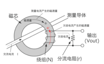
Measurement principle.
a, In order to counteract the flux generated inside the core caused by the AC current flowing through the measurement conductor (primary side), an AC current corresponding to the turns ratio is flowing through the winding on the secondary side. b, In order to counteract the flux generated inside the core caused by the AC current flowing through the measurement conductor (primary side), an AC current corresponding to the turns ratio (secondary current)
b, This secondary current flows through the shunt resistor and generates a voltage across the shunt resistor. This voltage is output in proportion to the current flowing through the measurement conductor.

Features compared to other methods.
1, can only measure AC (can not measure DC)
2, the price is cheap
3, mainly used for 50/60Hz industrial frequency
4, used for energy-saving management of buildings and other use of the clamp-on power meter
5, can offset the magnetic flux, so the linearity is better
2. the Hall element way current sensor measurement principle
Hall element current sensor uses the principle of the magnetic field generated around the measurement current is converted to voltage through the Hall effect.

Measurement principle.
a, the magnetic flux generated inside the core caused by the current flowing through the measurement conductor (primary side) is passed through a Hall element inserted into the core gap using the Hall effect to appear as a Hall voltage corresponding to the magnetic flux.
b, This Hall voltage is very small, so it is the output signal that increases by AMP.
c, This output signal is proportional to the current flowing through the measurement conductor.
Features compared to other methods.
1, can measure from DC to AC (several kHz)
2, Inexpensive
3, due to the linearity of the Hall element, the core of the B-H characteristics of the impact, in general, the accuracy is not very good
4, Due to the characteristics of the Hall element, the temperature or the change of the elapsed time will cause drift, so it is not suitable for long time measurement.
5, The magnetic core will become a load, so it cannot be extended to high frequency band
3. Measurement principle of Rokowski method current sensor
The Rokowski method current sensor uses the AC magnetic field generated around the measurement current to convert the induced voltage of the hollow coil for measurement.

Measurement principle.
a, The magnetic field generated by the current flowing through the measurement conductor (primary side) is interconnected with the hollow coil, which generates an induced voltage.
b, This induced voltage is the time derivative value (di/dt) of the measurement current and is therefore the output signal proportional to the measurement current through the integrator.
Features compared to other methods.
1, because there is no magnetic core, so magnetic saturation does not occur and can measure large currents
2, no magnetic loss brought about by heat, saturation, hysteresis
3, the sensor part is hollow coil, can be flexible and slim
4, small impedance
5, can only measure AC, can not measure DC
6, measurement sensitivity is affected by the cross-section of the hollow coil and the length, so it is susceptible to the influence of the conductor position or foreign interference, and can not expect high-precision measurement.
7, no magnetic core, so it is difficult to measure the small current below 10A
4. AC zero flux mode (winding detection type) of the current sensor measurement principle
AC zero flux method current sensor (winding detection type) improves the low frequency band characteristics of the CT method.

Measurement principle.
a, In order to eliminate the magnetic flux Φ generated inside the core caused by the AC current flowing through the measurement conductor (primary side), a secondary current corresponding to the turns ratio of the feedback winding on the secondary side is flowed.
b, the magnetic flux in the low frequency band is not eliminated and will be residual flux
c. This incomplete flux is detected by the detection winding and flows through the secondary current to remove the flux Φ through the AMP circuit.
d, this current flows through the shunt resistor and generates a voltage across the shunt resistor
e. This voltage is output in proportion to the current flowing through the measurement conductor.
Features compared to other methods.
1, because it is a negative feedback operation that eliminates the magnetic flux inside the core, it is not affected by the B-H characteristics of the core and has excellent linearity
2, Phase error at low frequencies is also very small, so it is suitable for power measurement
3, The working flux level is small, so the insertion impedance is low
4, working as CT in high frequency band, thus achieving wide frequency
5, the use of windings for detection, so only measure AC current, can not measure DC current
5. AC/DC zero flux mode (Hall element detection type) current sensor measurement principle
AC/DC zero flux type current sensor (Hall element detection type) can measure from DC current by using CT method and Hall element.

Measurement principle.
a, In order to eliminate the magnetic flux Φ generated inside the core caused by the AC current flowing through the measurement conductor (primary side), a secondary current corresponding to the turns ratio of the feedback winding on the secondary side is flowed.
b, In the low frequency band starting from DC, the magnetic flux is not eliminated and will be residual flux
c. The Hall element is used to detect this incomplete flux removal, and the secondary current flows through the AMP circuit to remove the flux Φ
d, this current flows through the shunt resistor and generates a voltage across the shunt resistor
e. This voltage is output in proportion to the current flowing through the measurement conductor.
Features compared to other methods.
1, excellent linearity characteristics, even low level to maintain high accuracy
- High S/N ratio is achieved in the wide band
3, Works as a CT in the high frequency band, so a wide range of frequencies can be achieved
4, Using Hall elements for detection, magnetic detection from DC, so it can be measured from DC current

6. AC/DC zero flux method (flux gate detection type) current sensor measurement principle
The AC/DC zero flux method (flux gate detection type) current sensor can measure from DC current by cooperating with the FG element (flux gate) through the CT method.

Measurement principle.
a, In order to eliminate the magnetic flux Φ generated inside the core caused by the AC current flowing through the measurement conductor (primary side), a secondary current corresponding to the turns ratio of the feedback winding on the secondary side is flowed.
b, the low frequency band starting from DC, the magnetic flux is not eliminated and will be residual flux
c. The FG element detects this incomplete flux and flows the secondary current to remove the flux Φ through the AMP loop.
d, this current flows through the shunt resistor and generates a voltage across the shunt resistor
e. This voltage is output in proportion to the current flowing through the measurement conductor.
Features compared to other methods.
1, excellent linearity characteristics, even low level to maintain high accuracy
2, Small working flux level, therefore low insertion impedance
3, The FG element for detecting DC has a very small offset over a wide temperature range in its operating principle, achieving high accuracy and stability.