Get to know Parallel Flash
As we know, the number of ECUs in a car can be as few as a few dozen or as many as a hundred. Suppose a scenario where some of the ECU functions fail due to some reasons and the application program of these ECUs need to be updated again, if we update them one by one, it will definitely take some time, and as a consumer, we always want our car to be repaired quickly, why not the maintenance staff? So, Parallel Flash and Queued Flash are here.

Then again, in the vehicle off the line EOL (End of Line), the factory to pursue efficiency, generally will be 1 (brush the upper computer) tow N (N ECU) brush write, which is not a kind of Parallel Flash it?
Again, Queued Flash is for a single ECU and Parallel Flash is for multiple ECUs, and both technologies can be used simultaneously. In this article, let’s get to know Parallel Flash.
1。Network topology of the whole vehicle
Before understanding Parallel Flash, let’s get to know the network topology of the whole vehicle. To make it easier to understand, we will simply show the network topology of the whole vehicle. There are not only Can bus, but also Ethernet, Flexray and Lin bus in the whole vehicle network.
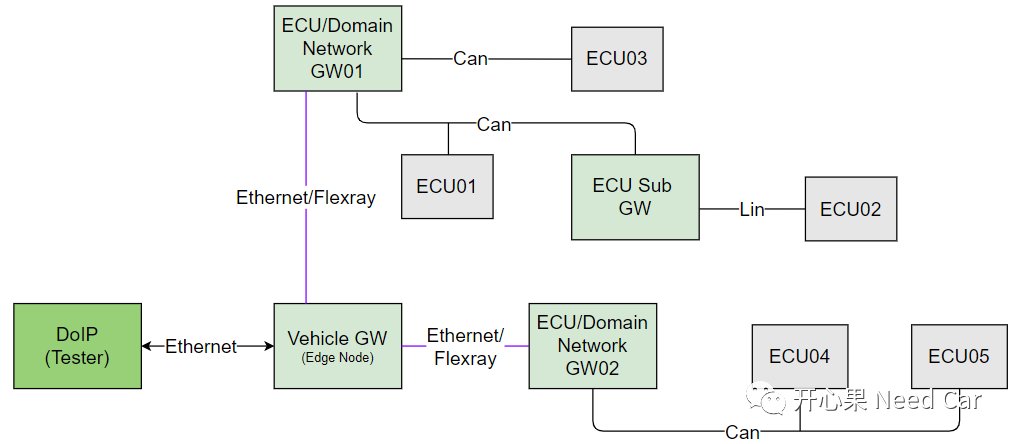
As shown above, the gateways in the whole vehicle can be divided into three types: Vehicle GW (Edge Node), ECU/Domain Network GW, and ECU Sub GW.
Vehicle GW (Edge Node) : communicates with external devices (Tester) via Ethernet, also called Edge Node. The Edge Node is connected to the domain gateway through the backbone, which will choose a bus with relatively high rate, such as: Ethernet/Flexray.
ECU/Domain Network GW : Domain gateway, the whole vehicle will be divided into multiple domains such as power domain, video and audio domain. The domain gateways are connected to sub gateways or terminal ECUs, and can communicate with each other through Can/Lin buses with relatively low rates.
ECU Sub GW: sub gateway, under the sub gateway, the terminal ECU will be connected, and the communication between the sub gateway and the terminal ECU can be through Can/Lin bus.
Since the rate of Ethernet is fast, why so many buses? Although Ethernet is fast, but the cost is high, so the EE department of OEM will consider the choice of bus in the topology design of the whole vehicle.
2。Parallel Flash Brush Flow
Suppose there are two ECUs: ECU01 and ECU02 need to be flushed at the same time, and both ECU01 and ECU02 are hooked up under the sub-gateway GW-S, which is under the central gateway GW-C, and the upper computer (Tester) does the flushing via Ethernet (DoIP). Two cases are discussed here.
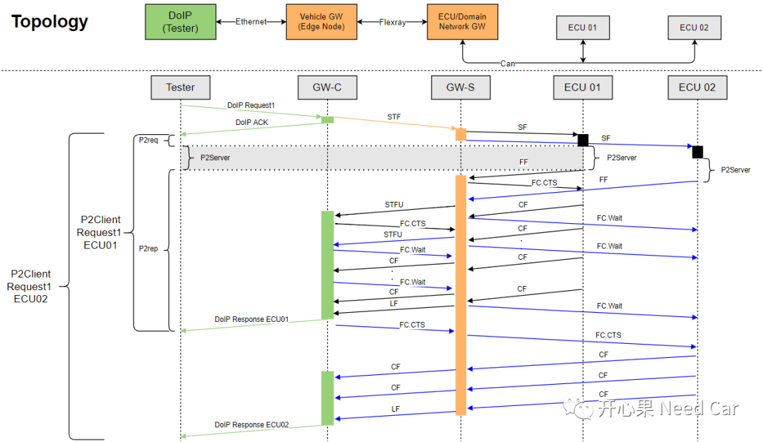
First: GW’s lack of processing power
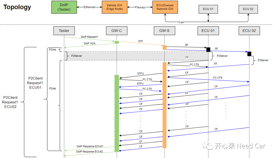
Second: GW processing power is sufficient
1、Explanation of brush writing process
Assumptions: Send $19 02 08 service with functional addressing, read ECU01 and ECU02 fault messages, reply message requires multiple frame transmission.
Hint: Discussion based on the first scenario
The Tester sends a functional addressing diagnostic request (Request1 = $19 02 08) to the GW-C via DoIP.
The GW-C will immediately answer the host (since the DoIP diagnostic request uses the Tcp protocol), which is equivalent to the ACK answer mechanism of the Can bus, while routing Request1 to the GW-S via the Flexray bus;
GW-S further routes Request1 from the Flexray bus to the Can bus to ECU01 and ECU02.
ECU01 and ECU02 give their response in their respective P2Server time, i.e.: First Frame (FF:Frist Frame). CTS (continue sending consecutive frames, note: physical addressing is used here to send to ECU01), let ECU01 send the CF (Executive Frame) first, and let ECU02 wait for ECU01 to finish processing (send FC.Wait to ECU02, physical Wait, physical addressable send flow control wait), and when the GW-S has finished processing ECU01, then send FC.CTS (physical addressable send) to ECU02 to complete the processing of ECU02.
The GW-S converts the FF from the Can bus into the STFU (Start Frame Unacknowledged) of the Flexray, and then routes it to the GW-C through the Flexray bus;
The GW-C receives the ECU01 LF (Last Frame) frame from the GW-S and responds to the Tester (DoIP Response ECU01);
The GW-C receives the ECU02 LF (Last Frame) frame forwarded by the GW-S and responds with a Tester (DoIP Response ECU02).
2、Problem expansion
First: As can be seen in the above swipe process, the diagnostic command Request1 goes through GW-C, GW-S, to the diagnostic command is processed (P2Server time), the routing consumes a lot of time, from this perspective, you can understand why the OEM will constrain the strict routing time, it is to improve the rate of swipe writing.
Second: the diagnostic request for functional addressing is not only sent to the terminal ECU (for example: the above ECU01 and ECU02), the GW node also needs to process the diagnostic command (for example: the above GW-C, GW-S).
Third: We often see the constraint: ” When a functionally addressed $3E 00/80 instruction and a physically addressed non-$3E 00/80 instruction request an ECU at the same time, the functionally addressed $3E 00/80 instruction needs to be processed first”. Why? After all, it is more important to keep the node in the programming session.
Fourth: What we saw above is that DoIP sends functional addressing to ECU01 and ECU02, which is the same instruction sent to different ECUs . And there is another case in Parallel Flash where DoIP sends physically addressed commands to ECU01 and ECU02 respectively (e.g., $10 01), why is it feasible? In general, the Ethernet bus rate is 100Mbps, while the Can bus rate is 500kbps. The Ethernet bus rate is 200 times higher than the Can bus communication rate, and its data processing capability is sufficient to support Ethernet to send different diagnostic commands to a certain number of ECUs using physical addressing at ****, and to process the response data of each ECU. data.
Fifth: There is a delay in the routing of commands with each GW pass.
Sixth: Whether the GW processing capability is sufficient or not depends on whether the resources of the main chip are sufficient. Although opening up more RAM to process diagnostic instructions can make the swipe rate faster (the second case in the figure above), the resource overhead faced is also considerable. Especially when the bus conversion, TP layer, PduR module all need to overhead resources, and the overhead volume is not small.