There are various interfaces of LCD, and the classification is very fine. Mainly depends on the LCD drive mode and control mode, the current color LCD on the phone is generally connected to so many ways: MCU mode, RGB mode, SPI mode, VSYNC mode, MDDI mode, DSI mode. MCU mode (also written as MPU mode). Only TFT module has RGB interface.
But more applications are MUC mode and RGB mode, the differences are as follows.

1.MCU interface:It will decode the command and generate timing signal by TIming generator to drive COM and SEG driver.
RGB interface:There is no difference with MCU interface when writing LCD register setTIng. The difference only lies in the way the image is written.
- In MCU mode, the data can be stored in the internal GRAM of the IC before writing to the screen, so the LCD can be directly connected to the MEMORY bus in this mode.
When using RGB mode, it is different, it has no internal RAM, HSYNC, VSYNC, ENABLE, CS, RESET, RS can be directly connected to the GPIO port of MEMORY, and the GPIO port is used to simulate the waveform.
- MPU interface mode: display data is written to DDRAM, often used for still picture display. RGB interface mode: display data is not written to DDRAM, directly write the screen, fast, often used for displaying video or animation.
The main difference between MCU interface and RGB interface is: MCU interface method: display data is written to DDRAM, often used for still picture display. RGB interface method: display data is not written to DDRAM, directly write screen, fast, often used for displaying video or animation.
MCU mode is named because it is mainly used in the field of microcontrollers. The standard term for MCU-LCD interface is the 8080 bus standard proposed by Intel, so in many documents, I80 is used to refer to MCU-LCD screens. Mainly can be divided into 8080 mode and 6800 mode, the main difference between the two is the timing. Data bit transfer is 8-bit, 9-bit, 16-bit, 18-bit, 24-bit. Connecting lines are divided into: CS/, RS (register selection), RD/, WR/, and then the data line. The advantages are: simple and convenient control, no need for clock and synchronization signal. The disadvantage is: it consumes GRAM, so it is difficult to do large screen (more than 3.8). For the MCU interface LCM, its internal chip is called LCD driver. The main function is to transform the data/commands sent by the host into RGB data for each pixel, so that it can be displayed on the screen. This process does not require dot, line, or frame clocks.
The Driver IC of the MCU interface LCD is with GRAM, the Driver IC acts as a co-processor of the MCU, accepting the Command/Data sent from the MCU, and can work relatively independently. For the MCU interface LCM (LCD Module), the internal chip is called LCD driver. The main function is to transform the data/commands sent by the host into RGB data for each pixel to be displayed on the screen. This process does not require a dot, line, or frame clock.
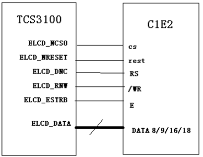
M6800 mode M6800 mode supports selectable bus width 8/9/16/18-bit (default is 8-bit), the actual design idea is the same as that of I80, the main difference is that the bus control read/write signal of this mode is combined on one pin (/WR), while adding a latch signal (E) data bit transmission with 8-bit, 9-bit, 16-bit and 18-bit.
I8080 mode I80 mode connected lines are divided into: CS/, RS (register selection), RD/, WR/, and then the data line. The advantages are: simple and convenient control, no need for clock and synchronization signal. The disadvantage is: to consume GRAM, so it is difficult to do large screen (QVGA or above).
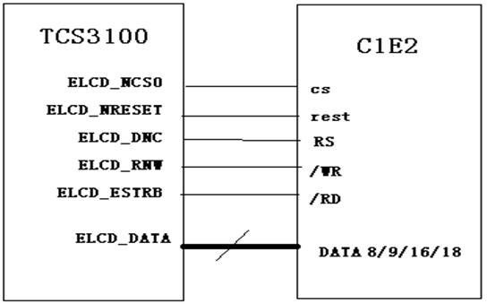
MCU interface standard name is I80, the pin control pin has 5: CS chip select signal RS (set 1 for write data, set 0 for write command)/WR (0 for write data) data command distinguish signal/RD (0 for read data) RESET reset LCD ( with fixed command series 0 1 0 to reset) VSYNC mode
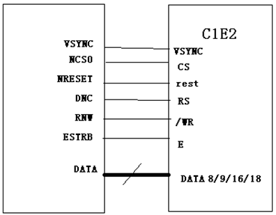
This mode is actually the MCU mode with a VSYNC signal applied to the motion picture update, which makes a big difference from the two interfaces mentioned above. This mode supports the function of direct animation display, which provides a solution to achieve animation display with minimal changes to the MCU interface. In this mode, the internal display operation is synchronized with the external VSYNC signal. It is possible to achieve an animated display with a higher rate than the internal operation. However, due to the difference in its operation, this mode has a limitation on the rate, that is, the write rate to the internal SRAM must be greater than the rate at which the display reads the internal SRAM.
RGB mode large screen using more modes, data bit transmission also has 6-bit, 16-bit and 18-bit, 24-bit points. Connecting lines are generally: VSYNC, HSYNC, DOTCLK, CS, RESET, some also need RS, the rest is the data line. Its advantages and disadvantages are exactly the opposite of MCU mode.
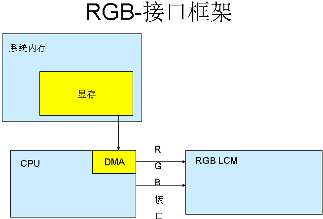
The main difference between MCU-LCD screen and RGB-LCD screen is the location of the video memory, the video memory of RGB-LCD is filled by the system memory, so its size is only limited by the size of the system memory, so RGB-LCD can make a larger size, like nowadays 4.3″ can only be considered as the entry level, while MID 7″ and 10″ screens are used in large numbers. The MCU-LCD is designed with the small memory of the microcontroller in mind, so the memory is built into the LCD module. Then the software updates the memory through special display commands, so the MCU screen often cannot be made very large. Also, the display update speed is slower than RGB-LCD. There is also a difference in the display data transfer mode: RGB screens only need the memory to organize the data. After starting the display, LCD-DMA automatically sends the data in the video memory to the LCM through the RGB interface, while the MCU screen needs to send the command of drawing points to modify the internal RAM of the MCU (i.e., the RAM of the MCU screen cannot be written directly). So the RGB display is significantly faster than the MCU, and the MCU-LCD is slower in playing video.
For LCM with RGB interface, the host output is directly RGB data per pixel without transformation (except for GAMMA correction, etc.). For this interface, there needs to be an LCD controller in the host part to generate RGB data and point, line and frame synchronization signals.

There are two main interfaces for color TFT LCDs: TTL interface (RGB color interface) and LVDS interface (RGB color packaged into differential signal transmission); TTL interface is mainly used for small size TFT screens under 12.1″ and LVDS interface is mainly used for large size TFT screens over 8″. LVDS interface has long transmission distance and less number of lines. Large screens use more modes, the control pins are VSYNC, HSYNC, VDEN, VCLK, S3C2440 supports up to 24 data pins, the data pin is VD[23-0].
The image data from the CPU or graphics card is a TTL signal (0-5V, 0-3.3V, 0-2.5V, or 0-1.8V), and the LCD itself receives a TTL signal. Since TTL signals perform poorly at high rates over long distances and are relatively immune to interference, a variety of transmission modes have since been proposed, such as LVDS, TDMS, GVIF, P&D, DVI and DFP, etc. They actually just encode the TTL signal from the CPU or graphics card into various signals for transmission, and decode the received signal on the LCD side to get the TTL signal.
However, the essence of the TTL signal is the same regardless of the transmission mode used.
Note: TTL/LVDS are two signal transmission modes respectively. TTL is a mode where high level means 1 and low level means 0. LVDS is a mode where positive and negative waveforms are used to indicate whether the current is 1 or 0 SPI by the difference between the two waveforms.
There are 3-wire and 4-wire modes with four wires: CS/, SLK, SDI, and SDO, which are less connected but more complicated to control by software.
MDDI mode (MobileDisplayDigitalInterface) Qualcomm proposed in 2004 interface MDDI, by reducing the number of lines can improve the reliability of cell phones and reduce power consumption, which will replace the SPI mode and become a high-speed serial interface in the mobile field. Connections are mainly host_data, host_strobe, client_data, client_strobe, power, GND a few lines.
DSI mode This mode is a serial bi-directional high-speed command transmission mode, the lines are D0P, D0N, D1P, D1N, CLKP, CLKN.