Differential Amplifiers
Differential amplifiers are different from ordinary op-amps in that they do not require an external resistor to form a differential amplifier circuit, which amplifies the difference between two signals by a specific multiple.
The differential amplifier integrates the resistors external to the op-amp’s subtractive circuit into the op-amp and uses laser trimming technology to adjust the resistance value of the resistors to a high degree of accuracy in order to reduce errors.
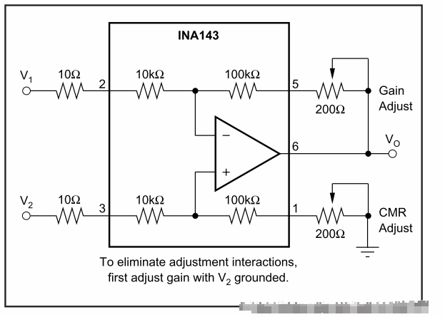
The following is an example of the INA143.
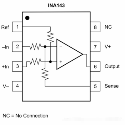
As can be seen in the diagram above, the INA143 has integrated resistors inside to directly form the differential amplifier. Here are a few ways of connecting this differential amplifier.

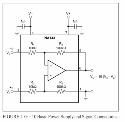
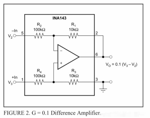
A differential amplification of 10 times is shown above, and due to the symmetry of the resistor structure, the reverse can also constitute a differential amplification of 0.1 times as shown below.
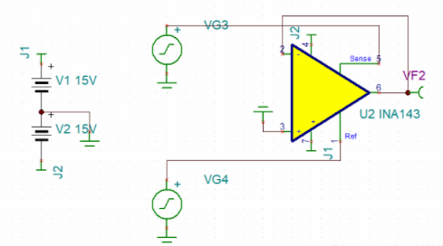
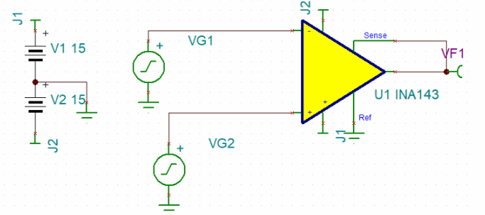
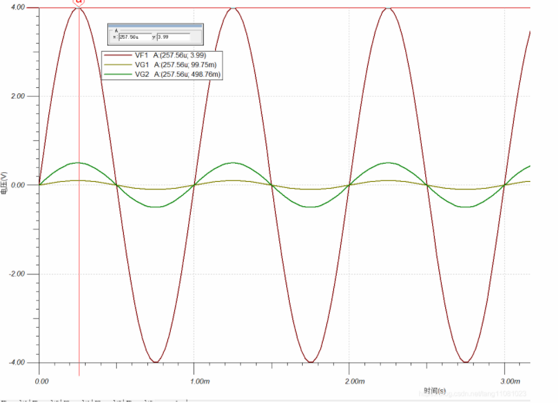
The following figure shows the simulation results for 10x differential amplification.
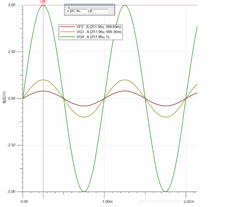
The following figure shows the results of 0.1x differential amplification.
Caution.
The differential amplifier should not be connected to an external resistor or to a small high-precision resistor, otherwise it will be a foregone conclusion for the following reasons.
As seen in the above diagram, the external resistor and signal source internal resistance if too high will be equivalent to the input resistance of the op-amp, then there will be the same error as the differential amplifier circuit.