Controlling DC Bias Circuits
This article is about using op-amps to build a subtractive circuit to control DC bias.
Since the vast majority of ADCs are unipolar, the signal needs to be changed from bipolar to unipolar before it is fed to the ADC for sampling. This is usually done by shifting the signal in a positive direction.
By the same token, most DACs are also unipolar, so if you need to output a bipolar signal, you need to translate the unipolar signal into a bipolar signal.
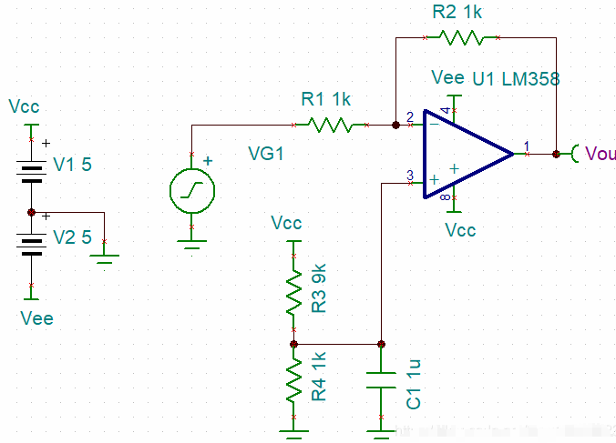
The diagram above shows a signal panning circuit.

Signal panning is achieved by superimposing level signals.
As can be seen by the circuit diagram, the signal is amplified by taking -1 times the input from the inverted end. The in-phase side is amplified by a resistor dividing the voltage to reach 0.5V input taken at 2x. The transfer function through this circuit is then
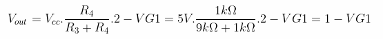
Can also be directly from the circuit’s superposition of the original mile directly available in the same phase input voltage of 0.5V inverted input voltage is
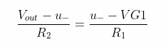
Substituting the data from the imaginary short gives
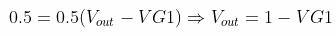
That is, the level is panned by 1V.
Simulation results.
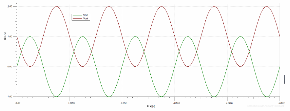
The DC voltage used to pan the signal must be of low internal resistance, so capacitor C1 is essential. Parallel connection of a large capacitor reduces the AC impedance.