Our most commonly used inductors are.
Ferrite core’s, wirewound process, plain shielded or resin shielded high power inductors.
Expensive metal one-piece molded inductors.
Small power inductors with ferrite substrate lamination process
RF inductors with laminated ceramic substrates
What is the meaning of the above modifier before “inductor”, this article tells you the answer.
1 Inductor Classification
Inductors are classified according to different categories, as explained in the following sections.
.

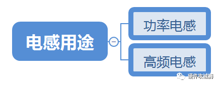
1.1 Inductor use: high frequency inductors
Used in RF circuits, to play the role of impedance matching, filtering, generally 0201 small size chip inductor
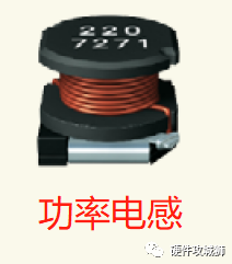
1.2 Inductor Usage: Power Inductor
Used in power supply circuits to act as a current continuity, such as in DCDC circuits. Generally larger in size, capable of passing several amps of current
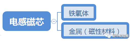
1.3 Inductive cores: ferrite cores
Cores made of ferrite, generally in the shape of an I-beam. The coil is wound on the ferrite, which can greatly improve the inductance. Ferrite a metal oxide with ferromagnetic properties. High resistivity, high permeability, and low saturation magnetization strength. Tends to lead to inductive magnetic saturation. Ferrite also has a feature of low eddy current loss, especially suitable for high frequency applications. For more information, see: Ferrite
Ferrite core wirewound inductors have been around for the longest time, are the most versatile, have the most mature processes, can achieve very large inductance values, and are the most widely used.
1.4 Inductor Cores: Metallic Magnetic Materials
A soft magnetic metal material that is not easily magnetically saturated and has good temperature characteristics. Magnetic saturation refers to the phenomenon that the magnetic flux through the magnetic material can not continue to increase. Magnetic saturation occurs in inductors with a magnetic core, but not in those without a magnetic core. High frequency inductors with an electrolytic ceramic core will not become magnetically saturated. The core of a metal inductor is a metallic magnetic material.
Power inductors made of metallic magnetic materials are generally one-piece inductors.
1.5 Inductor Shielding Method: Unshielded Inductors
The coil is rapped on the core without any shielding around it, and a significant portion of the magnetic flux leaks into the air, which interferes with the surrounding circuitry. External magnetic field will also interfere with no inductor work.
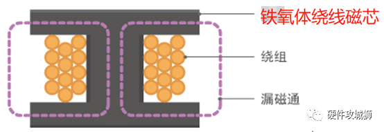
Two unshielded inductors, if examined very close together, the magnetic fields will interfere with each other and affect each other’s inductance values. Therefore unshielded inductors should be far away from each other!
1.6 Inductor shielding method: magnetic powder resin shielding inductor
The inductors are molded by mixing magnetic powder such as ferrite or soft magnetic metal with resin and filling it around the coiled core. This part of the magnetic powder can “lock” most of the electromagnetic field, but a part of the leakage out. Although the magnetic shielding effect is limited, the cost is low.

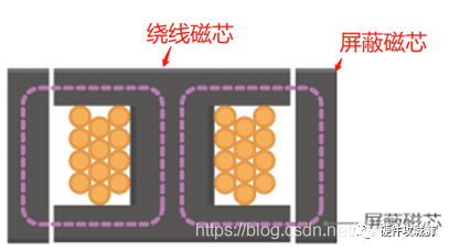
1.7 Inductive shielding method: Normal shielding
The type that covers the wire-wound core with a shielded core to form a near-closed magnetic circuit structure. The shielding core is made of the same material as the wire-wound core. This structure is not perfect because there is definitely a gap between the two cores and the electromagnetic field will leak out through the gap. Shielded cores have various shapes such as ring and L-shape.
1.8 Inductive shielding method: metal one-piece molding
This is the best shielding method. It is a hollow coil that has been wound and buried in a soft magnetic metal powder, and then pressed into shape as one piece. The soft magnetic metal powder is the winding core and the shielding core, both of which are completely integrated and have the least electromagnetic leakage.

The graphs below show the EMF leakage results of TDK’s three inductor series: VLS-EX series is resin shielded (semi-shielded), CLF-NI series is plainly shielded, and SPM series is metal one-piece molded power inductor.
EMF Leakage Strength: Resin Shield > Normal Shield > Metal One-piece Molded

Since inductors with ferrite cores are not well shielded, why do they continue to be used?
This is because power inductors with ferrite cores are characterized by a wider variety of inductors that can cope with higher inductance values. Their mass production is excellent and they are mostly used in various types of equipment.
Metal one-piece molded inductors are too expensive.
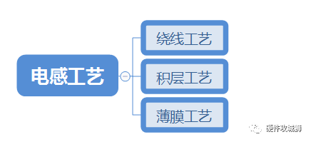
1.9 Inductor Process: Wirewound
Coarse copper wire is used to wind around the core to make inductors. Thick copper wire can reduce DC resistance and is suitable for high current scenarios.

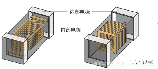
1.10 Inductive process: laminated type
Similar to MLCC, metal conductors are printed on a sheet substrate and then stacked layer by layer to produce coils. It is suitable for small-scale product scratching and ideal for mass production. The power of this type of inductor is generally not high. The base material for power inductors is ferrite, and the base material for high frequency inductors is ceramic.
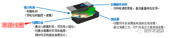
1.11 Inductor process: Thin film type:
By using a thin film process to form high-precision coils with metallic magnetic materials, the product is manufactured to suit small scratch and high current requirement applications.
2、Current characteristics of inductors
The inductor specification, as follows, will provide two current indicators.

Isat: Current based on inductance drop of 30%, indicating the DC superimposed allowable current, the inductance value when the inductance value drops by 30%.
Idc: Current based on an inductor temperature rise of 40°C. This indicates the allowable current based on a temperature rise of the inductor temperature from 20°C or 25°C (standards vary by manufacturer) up to 40°C.
The smaller of these two currents is the rated current of the inductor. The inductor operating current must not exceed this value!
2.1 Allowable DC superimposed current
The inductance value has the property of decreasing with increasing current, also called DC overlap characteristic. The current is so large that it reaches magnetic saturation, at which point the inductor loses inductance and the current immediately increases, burning out the inductor. It is important to avoid the magnetic saturation phenomenon in use.
Industry regulations require that specifications provide the inductance value corresponding to a 30% drop in inductance value, and the actual application current of the inductor, are not to exceed this value.
To put it another way, the inductor derating must not be less than 70%. The impression is that the automotive industry derating shall not be less than 90%.
2.2 Temperature Rise Allowable Current
As the current passes through the inductor, the inductor will heat up, and as the temperature rises, the characteristics of the core and winding will change, thus seriously affecting the inductor characteristics.
Industry specifications should provide the inductor temperature rise from 20°C or 25°C (different manufacturers’ standards) to 40°C allowable current. And the actual use shall not exceed this current.

3 Loss of inductor
Current through the inductor, the inductor temperature rises. The temperature rise comes from the loss of energy, the loss caused by the winding is called copper loss, the loss caused by the core material is called iron loss.
Copper loss is mainly caused by the resistance of the winding (Rdc). The copper loss caused by DC current is proportional to the square of the current. The copper loss caused by AC current is not only proportional to the square of the current, but also proportional to the frequency. The higher the frequency, the more the AC current will be concentrated near the surface of the conductor, skin effect makes the AC flu subject to greater impedance, AC copper loss is also greater.
Iron loss mainly includes hysteresis loss and eddy current loss. Eddy current loss is proportional to the second power of frequency, so the core loss caused by eddy current loss will increase in the high frequency range.

Idc’s test conditions will definitely have a frequency parameter, usually 1MHz.
The losses of power inductors vary depending on the size of the load. At small loads, there is almost no DC, and most of it is iron loss in the core material. At medium and heavy loads, the DC current is large, so it is mainly copper loss. The graph below shows the efficiency curve of a DCDC. The characteristics of the inductor directly determine the efficiency curve of the DCDC.

4、Trivia of inductor
4.1 Q value of inductors
Q value is a parameter that indicates the quality of an inductor. Q is short for Quality Factor. The coil will flow smoothly through the DC current, but will produce resistance to the AC current. This is called inductive reactance, and it increases with higher AC frequencies. In addition, although the winding is a conductor, it has a certain resistance component (R). The ratio of this resistance component to the inductance at the corresponding frequency (R/2πfL) is called the loss factor, the reciprocal of which is the Q value (Q=2πfL/R). f is the frequency of the current flowing through the coil, and the Q value changes with frequency. In short, the higher the Q value, the lower the loss, which is a very good characteristic for high frequency inductors.

For power inductors, it is rare to talk about Q value directly, but generally only look at the DC impedance, the smaller this value is, the better.
4.2 SRF
There is a small distributed capacity between the terminal electrode and the winding conductor, etc. in an inductor, so that resonance occurs at a specific frequency. The frequency at this point is called the self-resonant frequency. When the self-resonant frequency is exceeded, the inductor will not be able to perform its function.
When selecting an inductor for a high frequency circuit or high frequency module, it is important to consider not only the required inductance value, but also the self-resonant frequency relative to the frequency of use.
4.3 Inductors can be used in parallel
Inductors can be used in parallel, allowing them to pass more current when used in parallel. However, the disadvantage is that the inductance value decreases because it is a synthetic inductor. Synthetic inductance Lt can be calculated according to the following formula. (Inductors in parallel are similar to resistors in parallel)

4.4 Polarity of inductors
Inductors have their winding direction (polarity), so this symbol is marked to make it easier to confirm their polarity from the outside. Depending on the use case, the polarity of an inductor may affect its characteristics. On Apple’s motherboards, inductors are polarized and are required to be placed in the same direction when mounted.
High frequency inductors are also polarized, such as Murata’s LQP_T series, LQG series, and LQH series, and they are not constructed to be completely symmetrical, so such inductors must be handled according to polarized devices.
The following figure shows an example of how different inductor mounting directions will result in changes in inductance values.

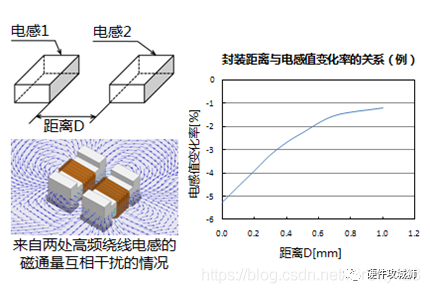
4.5 Inductive self-inductance and mutual inductance
Self-inductance means that the magnetic field of the inductor affects its own inductance value, and mutual inductance means that the inductor’s inductance value is affected by the external magnetic field. In use, self-inductance cannot be avoided, but mutual inductance should be avoided as much as possible.
The figure below shows the relationship between the distance between two high frequency inductors and the change in inductance value, so that an unshielded inductor is extremely susceptible to interference with other devices, and also susceptible to interference. In use, inductors are as far apart as possible.
4.6 Use inductors and capacitors to block the value of high-frequency interference
The high-frequency interference signal (red) as shown below passes through a small capacitor for the first time, and continues to propagate after being filtered out partially. After reaching the inductor, this high-frequency signal is bounced back (green arrow) due to the high impedance of the inductor, and is absorbed here after reaching the capacitor. The capacitor is in front of the inductor and this circuit filters out the high frequency signal tremendously.

5、Inductor and DCDC
In the field of baseband hardware, power inductors are only used in DCDC circuits, and they are an important component that affects the efficiency of DCDC. The following is a buck circuit, MOS tube open, the current stays through the inductor, into the load circuit, MOS tube off, due to the inductor current continuity characteristics (inductor current can not change suddenly), the inductor will try to suppress the current drop, at this time the inductor + capacitor + diode to form a loop.

5.1 DCDC requirements for inductors
DCDC has a close relationship with inductors. For an introduction to DCDC, see the upcoming article “DCDC and Inductors”. The requirements of DCDC for inductors can be briefly summarized as follows.

6、Metallic molded inductors
Many manufacturers are now pushing metal one-piece molded inductors. In terms of product structure, the magnetic shielding performance of this process is really the best, and the material properties of the core make the inductor less susceptible to magnetic saturation. The following is a comparison of the current performance of ferrite and metal cores: it is clear that metal cores are not easily magnetically saturated and can achieve greater current.

Magnetic leakage effect comparison: One-piece molding effect is very good.

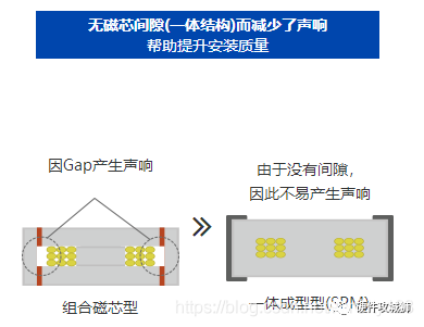
One-piece molded inductors have no core gap and are less prone to noise, which optimizes the inductor whine problem.
7, Steps of inductor selection
Determine the inductance value, this will be introduced in “DCDC and Inductors
Select the one whose maximum current does not exceed Isat and Idc.
Try to choose an inductor with a small DC resistance.
For high current applications, consider wirewound inductors or thin film inductors. High current applications should pay special attention to the shielding method of the inductor. If the motherboard device is dense and there are many sensitive devices, it is recommended to use an inductor with one piece molding. If not required, you can consider ferrite wirewound inductors or thin film inductors.
Small current applications, you can consider the product layer inductor, but also pay attention to the leakage flux on the surrounding devices interference.
Note that inductors should not be used at too high a temperature, which can affect Idc.