1 Preface
From the perspective of output dimension, vision sensor-based perception methods can be divided into two types: 2D perception and 3D perception. Previous articles of the column also provide detailed descriptions of these two perception tasks respectively.

In terms of the number of sensors, vision perception systems are divided into monocular, binocular, and multiocular systems. 2D perception tasks are usually performed with monocular systems, and this is the area where computer vision and deep learning are most closely integrated. Until the success of deep learning, it was common practice to infer the depth (distance) of a target based on assumptions such as the a priori size of the target and that the target is on the ground plane, or to use motion information for depth estimation (MoTIon Stereo). With the help of deep learning, learning scene cues from large datasets and performing monocular depth estimation becomes a feasible solution. However, this solution is very dependent on pattern recognition and it is difficult to handle scenes outside the dataset (Corner Case). For example, special construction vehicles on a construction road, the vision sensor cannot accurately detect the target and thus cannot determine its distance because there are few or no such samples in the database.
Binocular systems can naturally acquire parallax and thus estimate the distance to the obstacle. Such systems are less dependent on pattern recognition and can accomplish matching, calculate parallax and estimate distance as long as a stable key point on the target can be obtained. However, the binocular system also has the following drawbacks. First, if the key point is not available, such as the large white truck that often causes accidents in autonomous driving, if it crosses the middle of the road, it is difficult for the vision sensor to capture the key point in the limited field of view, and the distance measurement will fail. Second, binocular vision systems require very high calibration between cameras, and generally need to have very accurate online calibration. The cost of binocular system is between monocular and LIDAR, and some OEMs have started to use binocular vision to support different levels of autonomous driving systems, such as Subaru, Mercedes-Benz, BMW, etc.
Theoretically, binocular systems can already solve the problem of 3D information acquisition, so why do we still need multi-vision systems? There are two general reasons: first, to improve the adaptability to various environmental conditions by adding different types of sensors, such as infrared cameras; second, to extend the field of view of the system by adding cameras with different orientations and focal lengths. Here we will analyze several typical multi-eye systems.
2 Mobileye’s trinocular system
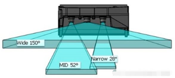
For a fixed-focus lens, the detection distance and detection angle are inversely proportional to each other. The wider the angle of view, the shorter the detection distance and the lower the accuracy; the narrower the angle of view, the longer the detection distance and the higher the accuracy. Car camera is difficult to do frequent zoom, so generally speaking the detection distance and field of view are fixed.
Multi-eye systems, which can cover different ranges of scenes by cameras with different focal lengths. For example, Mobileye and ZF jointly launched the trinocular system, which contains a 150° wide-angle camera, a 52° mid-range camera and a 28° telephoto camera. Its farthest detection distance can reach 300 meters, but also to ensure the detection field of view and accuracy of the medium and close range, used to detect the surrounding environment of the vehicle, and timely detection of objects that suddenly appear in front of the vehicle.
The main difficulty of this trinocular system is how to handle inconsistent perceptual results in the overlapping regions. Different cameras give different understandings of the same scene, and then it requires the fusion algorithm behind to decide which one to trust. Different cameras themselves have different error ranges, and it is difficult to design a reasonable rule to define the decision in various different situations, which brings more challenges to the fusion algorithm. As will be described later in the article, multi-vision systems can actually also use data layer fusion, using deep learning and large data sets to learn fusion rules. Of course it is not as if it is handed over to machine learning and that is the end of the story, black-box deep neural networks sometimes give unexplainable outputs.
3 Foresight’s four-eye perception system
Another idea for a multi-eye system is to add sensors of different wavelengths, such as infrared cameras (actually LIDAR and millimeter wave radar are also just sensors of different wavelengths). Foresight, an Israeli company, designed and demonstrated a QuadSight system. Based on the visible binocular camera, QuadSight adds a pair of long-wave infrared (LWIR) cameras to extend the detection range from the visible band to the infrared band. The addition of the IR band increases the amount of information on the one hand, and enhances the ability to adapt to nighttime environments and in rain and fog, ensuring the system’s ability to operate 24/7.
The QuadSight system has a 45-degree field of view and can detect objects up to 150 meters away, and can detect objects up to 35*25 cm in size at a distance of 100 meters. The operating speed can reach 45 frames per second, which is sufficient to deal with high-speed scenes.

The QuardSight system is composed of two pairs of binocular systems. As you can see in the picture above, the infrared binocular cameras are mounted on the left and right sides of the windshield, and their baseline length is much larger than a typical binocular system. Here is a slight digression to discuss the baseline length of the binocular system.
Traditional binocular systems generally use a short baseline mode, which means that the distance between the two cameras is relatively short, which limits the maximum distance of detection. When a target is far away, its parallax on the left and right images is already less than one pixel, and then it is impossible to estimate its depth, both the so-called baseline constraint. This is already the limit case, in fact, for long distance targets, even if the parallax is greater than one pixel, the error of depth estimation is still large. In general, the error in depth estimation should be proportional to the square of the distance.
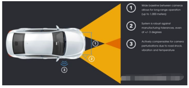
To improve the effective detection distance of binocular system, an intuitive solution is to increase the baseline length, which can increase the range of parallax. NODAR’s company introduced the Hammerhead technology, which can realize the wide baseline configuration of two cameras with extra-large distance, and the detection distance can be up to 1000 meters, while generating high-density point clouds. This system can take advantage of the entire width of the vehicle, for example by mounting the cameras on the side view mirrors, headlights or on the sides of the roof.
4 Tesla’s panoramic sensing system
After analyzing the tri- and quad-object examples, we move on to the focus of this post, which is a multi-object-based panoramic perception system. The example we use here is a purely visual FSD (Full Self Driving) system demonstrated by Tesla at AI Day 2021. Although it can only be considered as L2 level (the driver must be ready to take over the vehicle at any time), the performance of FSD is still good if we just compare L2 level autonomous driving systems side-by-side. In addition, this pure vision solution integrates many successful experiences in the field of deep learning in recent years, and is very characteristic in multi-camera fusion, which I personally think is worth studying at least in terms of technology.

Andrej Karpathy, the head of Tesla AI and Vision, was born in 1986 and received his PhD from Stanford University in 2015. applications in them. Musk brought this young talent on board in 2016 and has since put him in charge of Tesla’s AI department, where he is the chief architect of the algorithmic aspects of FSD, a pure vision system.
Andrej began his presentation at AI Day by saying that five years ago Tesla’s vision system started by obtaining the detection results on a single image and then mapping them to Vector Space. This “vector space” is one of the core concepts in the report, and I understand that it is actually the space where various targets in the environment are represented in the world coordinate system. For example, for the object detection task, the position, size, orientation, and velocity of the target in 3D space are described as a vector, and the space composed of all the description vectors of the target is the vector space. The task of the visual perception system is to transform the information in the image space into the information in the vector space. This can be achieved in two ways: first, by first performing all the perception tasks in image space, then mapping the results to vector space, and finally fusing the results from multiple cameras; second, by first transforming the image features to vector space, then fusing the features from multiple cameras, and finally performing all the perception tasks in vector space.
Andrej gives two examples to show why the first approach is inappropriate. First, due to perspective projection, perceptual results that look good in the image have poor accuracy in vector space, especially in regions at long distances. As shown in the figure below, the lane lines (blue) and road edges (red) are very inaccurate after projection into vector space and cannot be used to support autonomous driving applications.

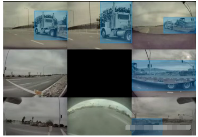
Second, in a multi-vision system, a single camera may not be able to see the complete target due to the limitation of the field of view. For example, in the example below, a large truck appears in the field of view of some cameras, but many cameras only see a part of the target, so they cannot make a correct detection based on the mutilated information, and therefore the subsequent fusion effect cannot be guaranteed. This is actually a general problem of multi-sensor decision layer fusion.
Combined with the above analysis, image space perception + decision layer fusion is not a good solution. Completing fusion and perception directly in vector space can effectively solve the above problems, which is the core idea of FSD perception system. In order to realize this idea, two important problems need to be solved: one is how to transform features from image space to feature space, and the other is how to get the labeled data in vector space.
4.1 Spatial Transformation of Features
For the problem of spatial transformation of features, the column has been introduced in the article of 3D perception before. The general approach is to use the calibration information of the camera to map the image pixels to the world coordinate system. However, this is a pathological problem that requires a certain constraint. The ground plane constraint is usually used in autonomous driving applications, which means that the target is located on the ground and the ground is horizontal. This constraint is too strong to be satisfied in many scenarios.
There are three points at the core of Tesla’s solution. First, the correspondence from image space to vector space is established by means of Transformer and Self-AttenTIon, and here the position encoding of vector space plays a very important role. The specific implementation details will not be expanded here, and will be introduced in detail in a separate article when we have time. In simple terms, the features of each position in the vector space can be regarded as a weighted combination of all the position features of the image, and of course the weight of the corresponding position must be larger. However, this weighted combination process is automatically implemented through Self-AttenTIon and spatial coding, which does not require manual design and is completely end-to-end learning based on the task to be accomplished.

Second, in mass production applications, the calibration information of the cameras in each vehicle is different, resulting in inconsistencies between the input data and the pre-trained model. Therefore this calibration information needs to be provided as additional input to the neural network. A simple approach could be to stitch together the calibration information of each camera, encode it by MLP and then feed it to the neural network. However, a better approach is to correct the images from different cameras by the calibration information so that the corresponding cameras on different vehicles all output consistent images.
Finally, the video (multi-frame) input is used to extract timing information to increase the stability of the output results, to better handle occlusion scenes, and to predict the motion of the target. An additional input to this part is the vehicle’s own motion information (available through the IMU) to support the neural network in aligning the feature maps at different points in time. The processing of the temporal information can be done using 3D convolution, Transformer or RNN. the RNN is used in FSD’s scheme, and in my personal experience, it is indeed the best balance between accuracy and computation.
With these algorithmic improvements above, the quality of FSD’s output in vector space has been greatly improved. In the comparison chart below, the output from the image space perception + decision layer fusion scheme is shown on the left below, while the above feature space transformation + vector space perception fusion scheme is shown on the right below.

4.2 Annotation in vector space
Since this is a deep learning algorithm, data and annotation are naturally key aspects. Tesla’s approach is to reconstruct a 3D scene using images from multiple cameras and perform annotation in the 3D scene. The annotator only needs to annotate the 3D scene once, and can see the mapping of the annotation results in each image in real time, so that it can adjust accordingly.

Manual annotation is only one part of the overall annotation system; to obtain annotations faster and better, automatic annotation and simulators are also needed. Automated annotation systems first generate annotation results based on single-camera images, and then integrate these results through various spatial and temporal cues. Figuratively speaking, the individual cameras come together to discuss a consistent annotation result. In addition to the cooperation of multiple cameras, multiple Tesla vehicles driving on the road can also fuse and improve the annotation of the same scene. Of course, GPS and IMU sensors are also needed here to obtain the position and attitude of the vehicles, so that the output of different vehicles can be spatially aligned. Automatic annotation can solve the annotation efficiency problem, but for some rare scenes, such as the pedestrians running on the highway demonstrated in the report, a simulator is also needed to generate virtual data. All of these technologies combined make up Tesla’s complete data collection and labeling system. The complete chain of work is still quite complex and will be discussed in a special article in the column afterwards.